Unlock instant, AI-driven research and patent intelligence for your innovation.
Garbage collection device for urban drain
What is Al technical title?
Al technical title is built by PatSnap Al team. It summarizes the technical point description of the patent document.
A garbage collection and drainage ditch technology, which is applied to water supply devices, drainage structures, grease/oily substances/floating matter removal devices, etc., can solve problems such as clogging in narrow and small drainage ditches, and achieve the effect of increasing the overall height
Active Publication Date: 2018-11-23
山东信开源科技创新发展有限责任公司
View PDF6 Cites 0 Cited by
Summary
Abstract
Description
Claims
Application Information
AI Technical Summary
This helps you quickly interpret patents by identifying the three key elements:
Problems solved by technology
Method used
Benefits of technology
Problems solved by technology
[0002] In big cities, most of the accumulated water on the road is drained into underground pipes, which is more convenient. However, in less developed cities or rural areas, ground drainage is still used, that is, drainage ditches are set on both
Method used
Image
Click on the blue label to locate the original text in one second.
Reading with bidirectional positioning of images and text.
Examples
Example Embodiment
Specific implementation one:
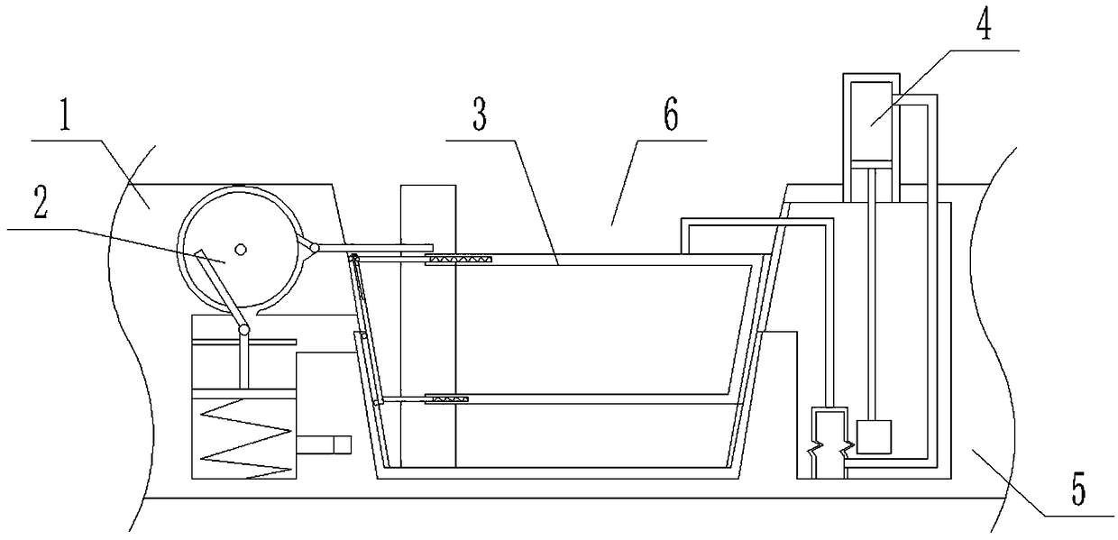
[0035] Combine below figure 1 , 2, 3, 4, 5, 6, 7, 8, 9, 10, 11, 12 illustrate this embodiment, the present invention relates to a garbage collection device, more specifically a garbage collection device for urban drainage ditch, including The left wall 1, cleaning device 2, blocking device 3, lifting device 4, right wall 5, and drainage ditch 6 can not only block the garbage in the drainage ditch, but also the filter device II can automatically rise according to the height of the water level, increasing the The overall height of the unit to prevent debris from drifting over the unit from the upper end of the unit.
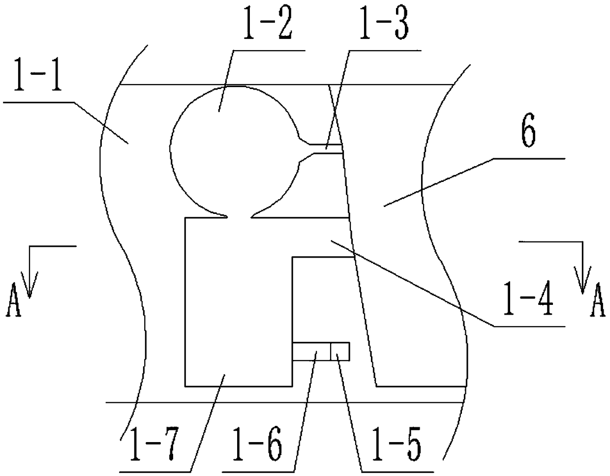
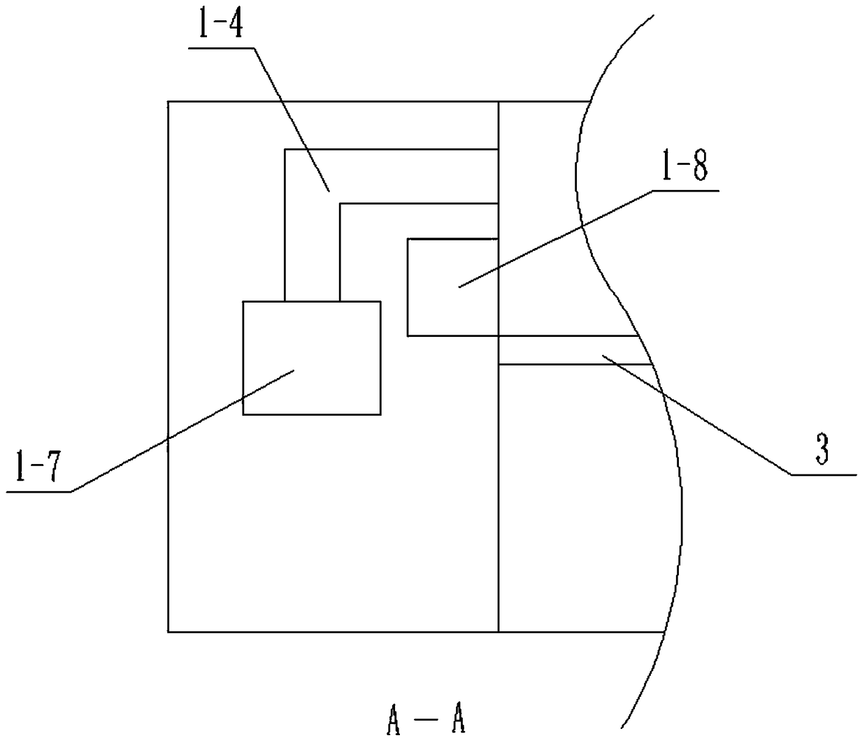
[0036] The left wall 1 consists of a left retaining wall 1-1, a circular groove 1-2, a horizontal groove I1-3, a horizontal groove II1-4, an auxiliary drainage groove 1-5, a communication groove 1-6, and a vertical groove 1- 7; the circular groove 1-2 is arranged on the inner upper end of the left retaining wall 1-1; the left end of...
Example Embodiment
Specific implementation two:
[0045] Combine below figure 1 , 2 , 3, 4, 5, 6, 7, 8, 9, 10, 11, and 12 describe this embodiment. This embodiment further describes Embodiment 1. The lower baffle 2-7 and the upper baffle 2-9 When the gap between them is communicated with the communication grooves 1-6, the upper baffle plate 2-9 is located in the vertical grooves 1-7.
Example Embodiment
Specific implementation three:
[0046] Combine below figure 1 , 2 , 3, 4, 5, 6, 7, 8, 9, 10, 11, and 12 describe this embodiment. This embodiment further describes Embodiment 1. The upper baffle 2-9 and the lower baffle 2-7 When both are located in the vertical grooves 1-7, the total weight of the water stored between the upper baffle 2-9 and the lower baffle 2-7 is greater than the elastic force of the spring I2-6.
PUM
Abstract
The invention relates to a garbage collection device for an urban drain, in particular to a garbage collection device for an urban drain. Not only can garbage in the drain be blocked, but also a filter device II can automatically rise according to the height of the water level, the overall height of the device is increased, and the phenomenon that the garbage floats through the device from the upper end of the device is prevented. The rotating shaft is arranged in a left retaining wall through a bearing; a transmission rod I and a transverse groove I are in clearance fit, and a transmission rod II and a transverse groove I are in clearance fit; a lower baffle and a vertical groove are in clearance fit, and an upper baffle and a vertical groove are in clearance fit; the lower end of a spring I is arranged at the bottom of the vertical groove; a brush makes contact with a filter screen I and a filter screen II; the drain is arranged between the left side wall and the right side wall; a fixing outer frame is fixedly arranged at the bottom of the drain; the left end of a U-shaped connecting rod is fixedly connected to the upper end of a U-shaped shell; the lower end of a cylinder II ona lifting cylinder is fixedly arranged at the bottom of a groove; the cylinder is fixedly arranged in a hole II.
Description
technical field [0001] The invention relates to a garbage collection device, in particular to a garbage collection device for urban drains. Background technique [0002] In big cities, most of the accumulated water on the road is drained into underground pipes, which is more convenient. However, in less developed cities or rural areas, ground drainage is still used, that is, drainage ditches are set on both sides of the road. If there is garbage in the drainage ditch , After the accumulation of garbage, it is easy to cause blockage in the narrow and small places of the drainage ditch, so this kind of garbage collection device for the drainage ditch is designed. Contents of the invention [0003] The invention provides a garbage collection device for urban drainage ditch. The beneficial effect is that it can not only block the garbage in the drainage ditch, but also the filter device II can automatically rise according to the height of the water level, increase the overall ...
Claims
Application Information
Patent Timeline
Application Date:The date an application was filed.
Publication Date:The date a patent or application was officially published.
First Publication Date:The earliest publication date of a patent with the same application number.
Issue Date:Publication date of the patent grant document.
PCT Entry Date:The Entry date of PCT National Phase.
Estimated Expiry Date:The statutory expiry date of a patent right according to the Patent Law, and it is the longest term of protection that the patent right can achieve without the termination of the patent right due to other reasons(Term extension factor has been taken into account ).
Invalid Date:Actual expiry date is based on effective date or publication date of legal transaction data of invalid patent.
