Check patentability & draft patents in minutes with Patsnap Eureka AI!

Projectile device launched by firearm

A technology of firearms and launching mechanisms, applied in the direction of launching devices, etc., can solve problems such as unstable launch trajectory, cloud movement and missed the best launch time, troublesome launcher displacement, etc.

Inactive Publication Date: 2018-11-23
福州市汇合兴机械设备有限公司
View PDF0 Cites 0 Cited by
  • Summary
  • Abstract
  • Description
  • Claims
  • Application Information

AI Technical Summary

Problems solved by technology

[0002] Artificial rainfall is based on the physical characteristics of different clouds, choose the right time to use airplanes and projectiles to spread catalysts into the clouds, so as to make the clouds precipitate or increase the precipitation, so as to alleviate the drought of farmland, increase the irrigation water volume or water supply capacity of the reservoir, and use the aircraft to spread the catalyst labor The strength is high, and there are many difficulties in the production, transportation, and storage of the catalyst, and it is easy to be restricted by flight conditions and flight schedules; now many small counties and cities use projectile projectiles for artificial rainfall. After tracking the rainable cloud layer, fix the rain bomb launcher on the ground and launch the projectile. Due to the changeability and mobility of the cloud layer, it often leads to missing the best launch time due to the long time spent after the launcher is installed and fixed. , it is extremely troublesome every time the launcher moves, and it will cause problems such as unstable launch trajectory

Method used


Image

  • Projectile device launched by firearm
  • Projectile device launched by firearm
  • Projectile device launched by firearm

Examples


Embodiment Construction

[0010] Combine below Figure 1-3 The present invention will be described in detail.

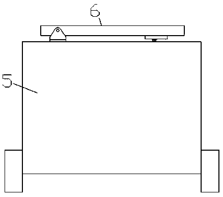
[0011] refer to Figure 1-3 According to an embodiment of the present invention, a projectile projectile device launched by a firearm includes a mobile vehicle body 5 and a launching mechanism 6 arranged on the top of the mobile vehicle body 5, and the top end surface of the mobile vehicle body 5 is provided with Transfer groove 51, in which the transfer groove 51 is rotated and connected with a support platform 8, the mobile car body 5 on the lower side of the transfer groove 51 is provided with a lift slide cavity 52, and the lift slide The cavity 52 is provided with a lifting and fixing mechanism, and the bottom wall of the lifting and sliding cavity 52 is symmetrically provided with through grooves 521 at the bottom end to communicate with the outside world. The bottom end surface of the support platform 8 is provided with a communication groove 82 at the top end which communicates with...


PUM


Abstract

The invention discloses a projectile device launched by a firearm. The projectile device comprises a moving vehicle body and a launching mechanism disposed on the top of the moving vehicle body, a transfer groove is formed in the top end face of the moving vehicle body, a supporting base is rotatably and cooperatively connected in the transfer groove, a lifting slide cavity is formed in the portion, on the lower side of the transfer groove, of the interior of the moving vehicle body and internally provided with a lifting fixation mechanism, and through grooves are symmetrically formed in the left and right sides of the bottom wall of the lifting slide cavity, wherein the bottom tail ends of the through grooves are communicated with the outside; a first sliding cavity is formed in the supporting base, and a communication slot is formed in the bottom end face of the supporting base, wherein the top tail end of the communication slot is communicated with the first sliding cavity; a gear ring is annularly fixed to the inner wall of the communication slot, and a first sliding block is slidingly and cooperatively connected in the first sliding cavity. A first motor is fixedly arranged inthe left end face of the first sliding block, and a first screw rod cooperatively in threaded connection with the left sidewall of the first sliding cavity is cooperatively in power connection with the tail end of the left side of the first motor.

Description

technical field [0001] The invention relates to the technical field of artificial rainfall, in particular to a projectile device launched by a firearm. Background technique [0002] Artificial rainfall is based on the physical characteristics of different clouds, choose the right time to use aircraft, projectiles to sow catalysts into the clouds, so that the clouds can precipitate or increase the amount of precipitation, so as to alleviate the drought of farmland, increase the irrigation water volume or water supply capacity of the reservoir, and use the aircraft to spread the catalyst labor The strength is high, and there are many difficulties in the production, transportation, and storage of the catalyst, and it is easy to be restricted by flight conditions and flight itineraries; now many small counties and cities use projectile projectiles for artificial rainfall. After tracking the rainable cloud layer, fix the rain bomb launcher on the ground and launch the projectile....

Claims


Application Information

Patent Timeline
Patent Type & Authority Applications(China)
IPC IPC(8): F41F1/00
CPCF41F1/00
Inventor 陈佳峰
Owner 福州市汇合兴机械设备有限公司
Features
  • R&D
  • Intellectual Property
  • Life Sciences
  • Materials
  • Tech Scout
  • Unparalleled Data Quality
  • Higher Quality Content
  • 60% Fewer Hallucinations
Learn More