
High temperature explosion-proof device of supercapacitor

A technology for supercapacitors and explosion-proof devices, which is applied in the protection/regulation of hybrid/electric double-layer capacitors, hybrid boxes/shells/packages, etc., can solve the problems of inconvenient installation, slow speed, poor explosion-proof effect of supercapacitors, etc., to avoid Effect of explosion accident and high temperature explosion prevention

Inactive Publication Date: 2018-11-23
HUNAN NEPUENERGY SCI & TECH
View PDF5 Cites 4 Cited by
  • Summary
  • Abstract
  • Description
  • Claims
  • Application Information

AI Technical Summary

Problems solved by technology

[0004] The purpose of the present invention is to provide a supercapacitor high temperature explosion-proof device to solve the problem of the speed of cooling the high temperature generated by the supercapacitor in the working state during the use of the existing supercapacitor high temperature explosion-proof device proposed in the above-mentioned background technology Slow, the thermal airflow around the supercapacitor is difficult to dissipate, which makes the explosion-proof effect of the device on the supercapacitor not good, which brings inconvenience to the device, and the device is prone to leakage, which affects the normal use of the device

Method used


Image

  • High temperature explosion-proof device of supercapacitor
  • High temperature explosion-proof device of supercapacitor
  • High temperature explosion-proof device of supercapacitor

Examples


Embodiment Construction

[0027] The following will clearly and completely describe the technical solutions in the embodiments of the present invention with reference to the accompanying drawings in the embodiments of the present invention. Obviously, the described embodiments are only some, not all, embodiments of the present invention. Based on the embodiments of the present invention, all other embodiments obtained by persons of ordinary skill in the art without making creative efforts belong to the protection scope of the present invention.

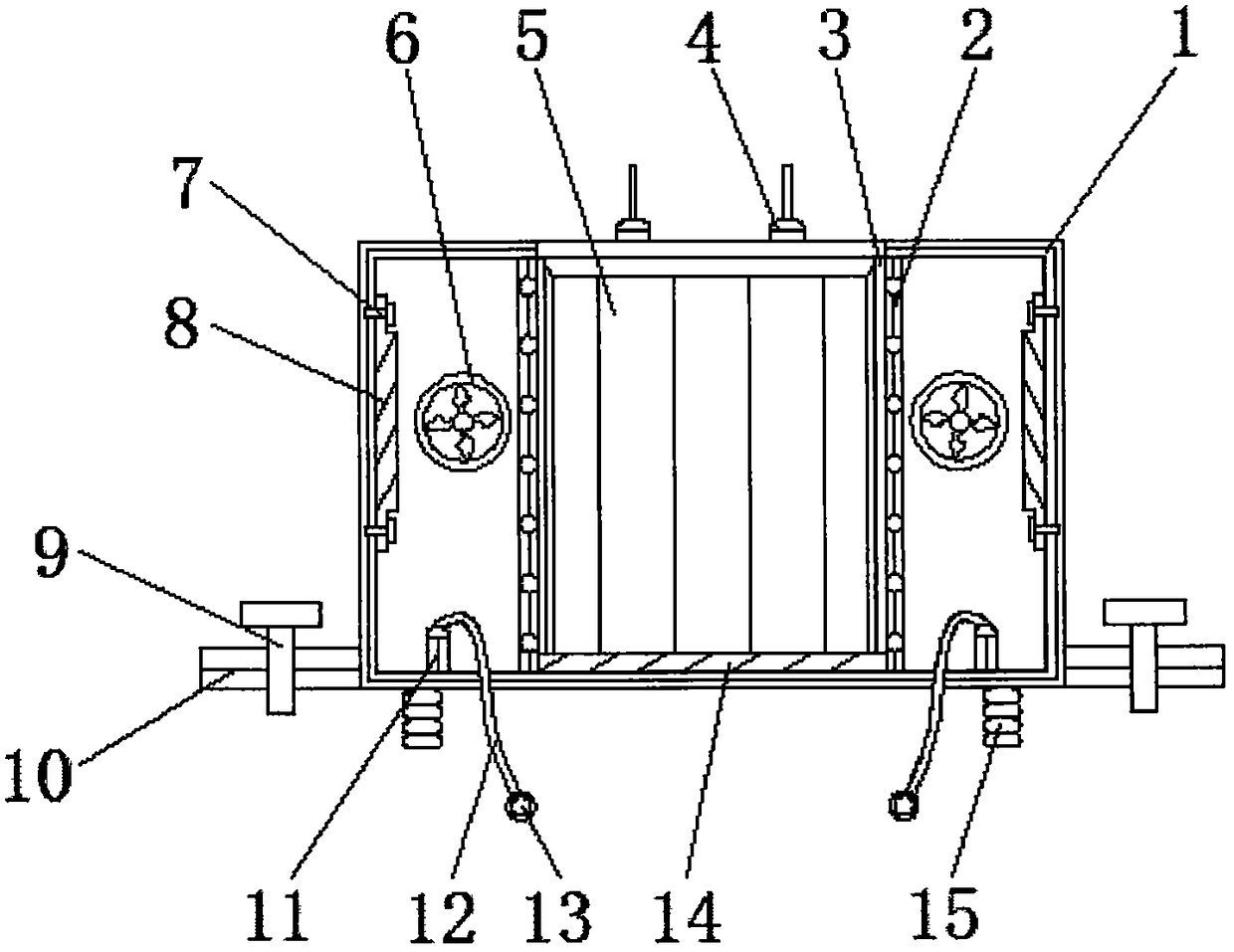
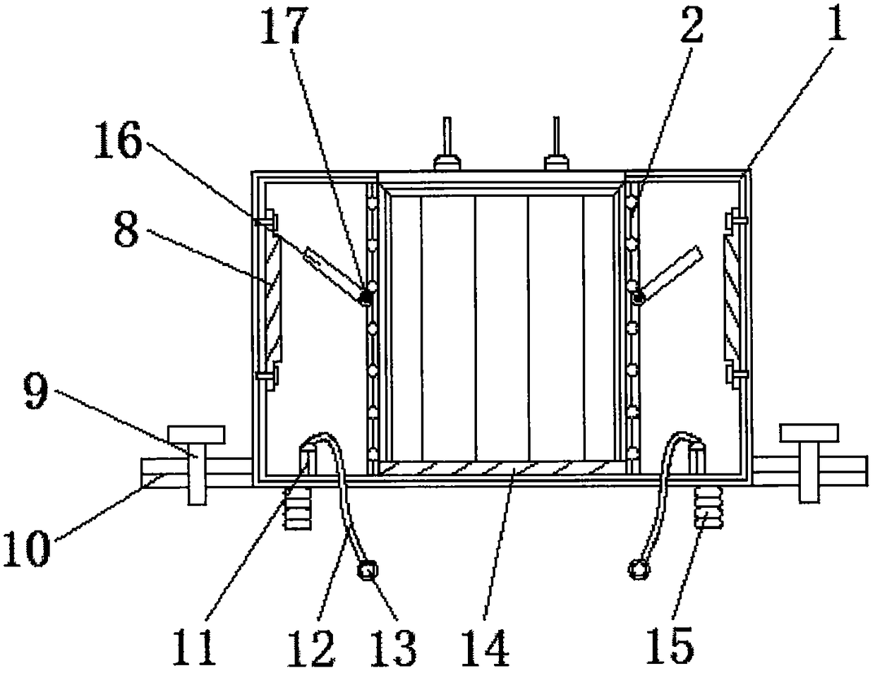
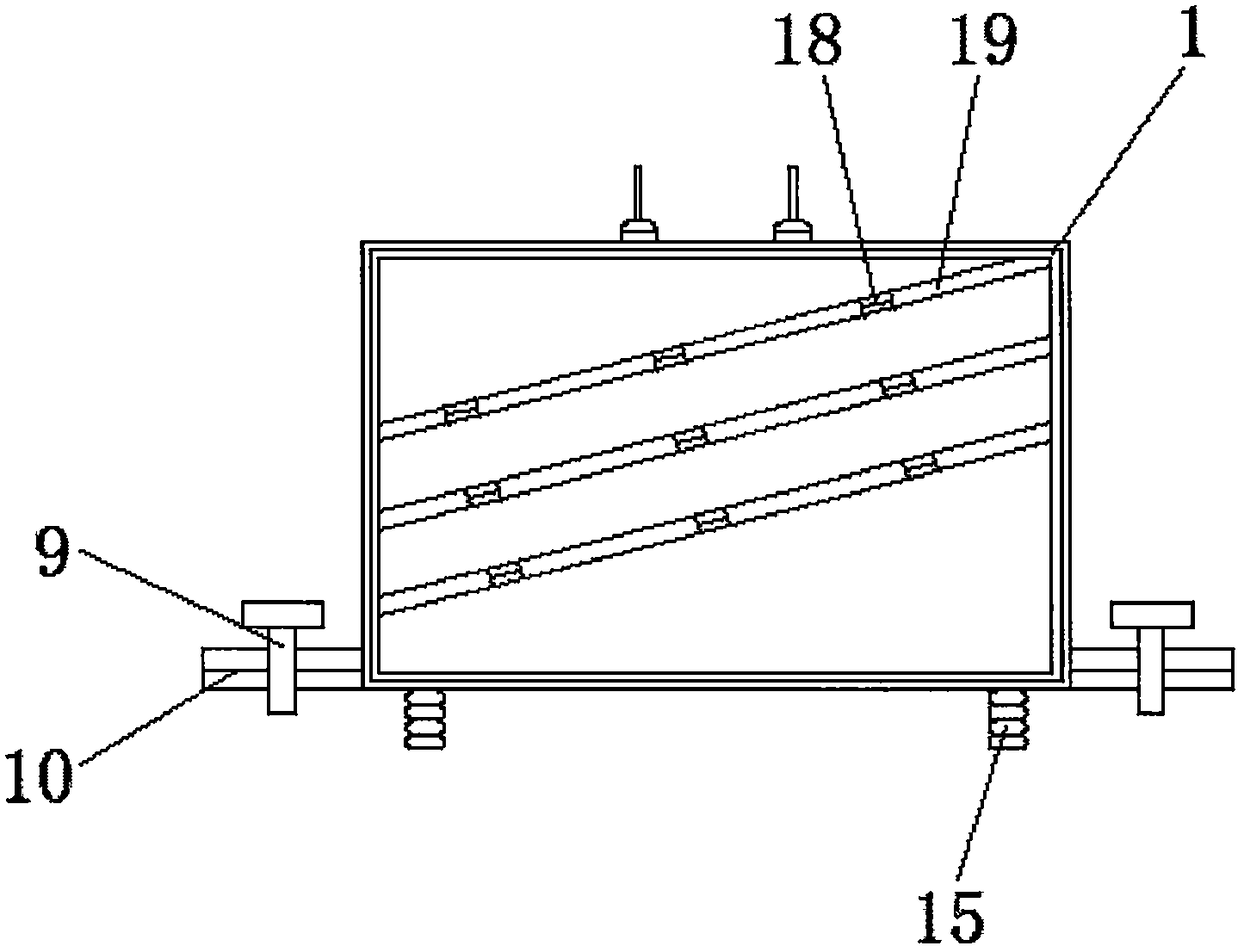
[0028] see Figure 1-6 , the present invention provides a technical solution: a high-temperature explosion-proof device for a supercapacitor, including a main body 1, a fixed plate 2, a chamber 3, pins 4, a capacitor body 5, a fan 6, a first bolt 7, a dust-proof net 8, Second bolt 9, fixed block 10, fixed column 11, grounding wire 12, connecting piece 13, shock absorbing pad 14, spring column 15, baffle plate 16, spring shaft 17, block 18, first reserved groov...


PUM


Abstract

The invention relates to a high temperature explosion-proof device of a supercapacitor. The device comprises a main body, a capacitor body and connecting pieces, wherein a fixing plate is mounted in the main body, and a cavity is fixed to an inner side of the main body, the capacitor body is disposed inside the cavity, and pins are disposed at the top end of the capacitor body. The high-temperature explosion-proof device of the supercapacitor has the following beneficial effects: according to the invention, the main body, the cavity, the capacitor body, the fixing plate, a baffle plate, a reserved port and a spring shaft are disposed, the baffle constitutes an elastic rotating structure through the spring shaft and the fixing plate, and by the action of the cavity, the capacitor body can be placed. When the capacitor body is in the working state, a high temperature is generated, so that the airflow around the capacitor body expands, the outward thrust of the baffle can be given, and the rotation of the spring shaft can drive he baffle to rotate to create a gap with the fixing plate, so that the hot air flow can be quickly exchanged with the cold air flow inside the main body, thereby effectively preventing the high temperature explosion phenomenon of the capacitor body.

Description

technical field [0001] The invention relates to the technical field of supercapacitor explosion protection, in particular to a supercapacitor high temperature explosion-proof device. Background technique [0002] With the development of science and technology and the progress of the social era, supercapacitors are more and more widely used, and supercapacitors refer to a new type of energy storage device between traditional capacitors and rechargeable batteries. At the same time, it has the energy storage characteristics of batteries. When supercapacitors are working, they generate high temperatures and are prone to explosions. They need to be explosion-proofed by supercapacitor high-temperature explosion-proof devices to avoid endangering people's lives. [0003] During the use of the existing supercapacitor high-temperature explosion-proof device, the speed of cooling the high temperature generated by the supercapacitor in the working state is slow, and the hot air around ...

Claims


Application Information

Patent Timeline
Patent Type & Authority Applications(China)
IPC IPC(8): H01G11/18H01G11/78
CPCH01G11/18H01G11/78Y02E60/13
Inventor 黄浩宇田超吴文
Owner HUNAN NEPUENERGY SCI & TECH
Learn More