Switch cabinet, cabinet body thereof and mutual inductor installation device

A technology for installing devices and transformers, applied in substation/switch layout details, electrical components, etc., can solve problems such as inconvenient replacement, and achieve the effect of avoiding transformer damage and simple installation structure

Active Publication Date: 2018-11-23
PINGGAO GRP +2
View PDF10 Cites 4 Cited by
  • Summary
  • Abstract
  • Description
  • Claims
  • Application Information

AI Technical Summary

Problems solved by technology

[0004] The purpose of the present invention is to provide a switchgear to solve the problem in the prior art that all transformers need to be dismantled and inconvenient to replace when performing transformer replacement operations; the purpose of the present invention is also to provide a switchgear Cabinet body and transformer installation

Method used


Image

  • Switch cabinet, cabinet body thereof and mutual inductor installation device
  • Switch cabinet, cabinet body thereof and mutual inductor installation device
  • Switch cabinet, cabinet body thereof and mutual inductor installation device

Examples


Embodiment Construction

[0060] Embodiments of the present invention will be further described below in conjunction with the accompanying drawings.

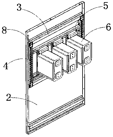
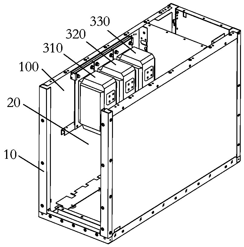
[0061] The specific embodiment of switchgear of the present invention, as Figure 2 to Figure 8 As shown, the switchgear includes a switchgear body 10 on which transformers and other electrical components (not shown in the figure) are installed. The switch cabinet body 10 in this embodiment includes a cable room 20 , and the transformer is installed on the side plate 100 of the cabinet body of the cable room 20 . Three transformers are installed on the side panel 100 of the cabinet body in this embodiment, respectively A mutual inductor 310, B mutual inductor 320 and C mutual inductor 330, and the three transformers are voltage transformers, wherein C The mutual inductor 330 is arranged close to the front end of the switch cabinet body 10 , and the A mutual inductor 310 is arranged near the rear end of the switch cabinet body 10 . For the convenience o...


PUM


Abstract

The invention relates to a switch cabinet, a cabinet body thereof and a mutual inductor installation device. The mutual inductor installation device comprises a sliding rail and a fixed structure andalso comprises a mutual inductor connection structure, wherein the sliding rail is used for being fixed on a side plate of the cabinet body, the fixed structure is used for fixing a mutual inductor onthe side plate of the cabinet body, the mutual inductor connection structure is used for being corresponding to a single mutual inductor and being fixed on the mutual inductor, the mutual inductor connection structure is matched with the sliding rail in a sliding way so that the single mutual inductor is assembled at a set position on the side plate of the cabinet body in a sliding way. The single mutual inductor is assembled in a sliding way, the external mutual inductor is only needed to be disassembled and replaced when a fault occurs in the external mutual inductor, and time and labor aresaved; and by the mutual inductor installation device, the problems that all mutual inductors are needed to be disassembled and are not convenient to replace during replacement operation of the mutual inductor in the prior art are solved.

Description

technical field [0001] The invention relates to a switch cabinet, its cabinet body, and a transformer installation device. Background technique [0002] At present, the switchgear in the switchgear is mostly arranged in a three-phase horizontal manner, and the width of the cabinet is generally more than 800mm. With the development of switchgear technology becoming more and more perfect, while improving the reliability of the switchgear, it is gradually becoming modular and small. direction of development. It is installed in a three-phase longitudinal arrangement, which can effectively utilize the depth dimension of the switchgear, thereby reducing the width dimension of the switchgear. Traditional transformers usually have four installation holes at the four corners of the transformer, and are installed in the cable room of the switch cabinet by four bolts. Only one installer can enter the cable room. When the transformer is installed in the longitudinal arrangement, the i...

Claims


Application Information

Patent Timeline
Patent Type & Authority Applications(China)
IPC IPC(8): H02B1/32
CPCH02B1/32
Inventor 祁海洋王海燕蒋成博袁端磊朱志豪卢健耿晓璐朱彦卿许东杰庞建田漪周建华
Owner PINGGAO GRP
Why Eureka
Try Eureka