Supercharge Your Innovation With Domain-Expert AI Agents!

Power takeoff device and engineering vehicle

A technology for mounting racks and working parts, which is applied to control devices, vehicle parts, auxiliary drive devices, etc., can solve problems such as inconvenience in installation, and achieve the effect of improving inconvenience in installation.

Pending Publication Date: 2018-11-30
XUZHOU XUGONG ENVIRONMENTAL TECH CO LTD
View PDF0 Cites 1 Cited by
  • Summary
  • Abstract
  • Description
  • Claims
  • Application Information

AI Technical Summary

Problems solved by technology

[0003] The present invention aims to provide a power take-off device and an engineering vehicle to improve the problem of inconvenient installation caused by the separation of the tensioning mechanism and the mounting bracket used to carry the working parts in the prior art

Method used


Image

  • Power takeoff device and engineering vehicle
  • Power takeoff device and engineering vehicle
  • Power takeoff device and engineering vehicle

Examples


Embodiment Construction

[0035] The following will clearly and completely describe the technical solutions in the embodiments of the present invention with reference to the accompanying drawings in the embodiments of the present invention. Obviously, the described embodiments are only some, not all, embodiments of the present invention. The following description of at least one exemplary embodiment is merely illustrative in nature and in no way taken as limiting the invention, its application or uses. Based on the embodiments of the present invention, all other embodiments obtained by persons of ordinary skill in the art without creative efforts fall within the protection scope of the present invention.

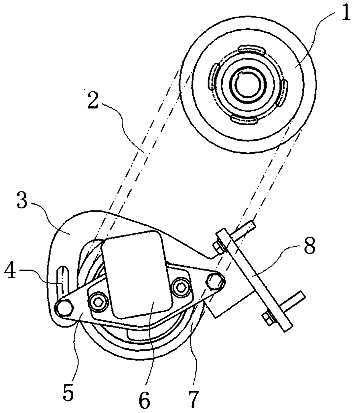
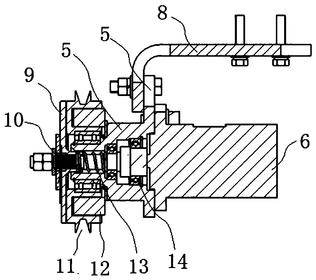
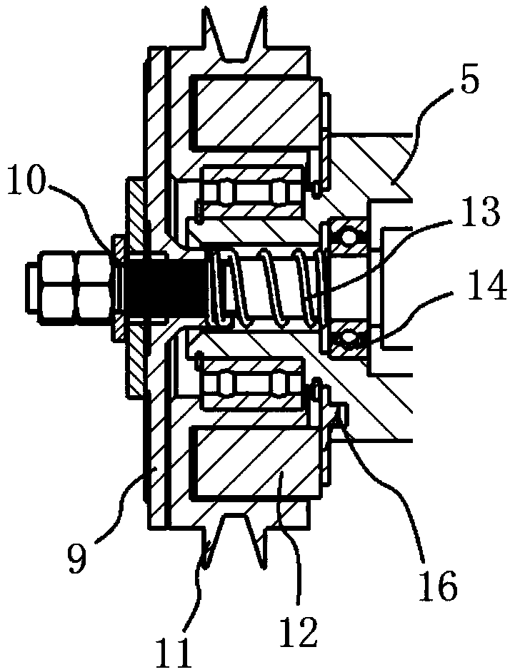
[0036] figure 1 A schematic structural view of the power take-off device of this embodiment is shown. figure 2 A cross-sectional view of the power take-off device of this embodiment is shown. image 3 show figure 2 A partial enlargement of the .

[0037] combine Figures 1 to 3 As shown, the p...


PUM


Abstract

The invention relates to a power takeoff device and an engineering vehicle. The power takeoff device comprises a working component (6), a flexible transmission component (2) used for connecting the working component (6) with an engine (1), and an installation frame used for being connected with the engine (1), wherein the working component (6) is installed on the installation frame, the relative positions of the working component (6) and the installation frame can be adjusted, and therefore the tensioning degree of the flexible transmission component (2) is adjusted. By the application of thetechnical scheme, the relative positions of the working component and the installation frame can be adjusted, so that the tensioning degree of the flexible transmission component is adjusted, and theproblem of inconvenient installation caused by separation of a tensioning mechanism and an installation support used for bearing the working component in the prior art is solved.

Description

technical field [0001] The invention relates to the field of engineering machinery, in particular to a power take-off device and an engineering vehicle. Background technique [0002] At present, for the special chassis of the vehicle that does not have a power take-off opening in the gearbox, it is necessary to take the power from the engine timing gear shaft. However, the existing power take-off device has low reliability and complex structure. The tensioning mechanism for adjusting the tension of the transmission belt is separated from the mounting bracket for carrying the working parts, which makes installation inconvenient. The ground clearance is small and the working process is difficult. It is easy to have problems such as the transmission belt falling off and the electromagnetic clutch not being absorbed smoothly. Contents of the invention [0003] The present invention aims to provide a power take-off device and an engineering vehicle to improve the problem of in...

Claims


Application Information

Patent Timeline
Patent Type & Authority Applications(China)
IPC IPC(8): B60K25/02B60K25/06
CPCB60K25/02B60K25/06B60K2025/022
Inventor 程磊单龙孔德军赵龙
Owner XUZHOU XUGONG ENVIRONMENTAL TECH CO LTD
Features
  • R&D
  • Intellectual Property
  • Life Sciences
  • Materials
  • Tech Scout
  • Unparalleled Data Quality
  • Higher Quality Content
  • 60% Fewer Hallucinations
Learn More