Robotic Arms

a technology of robotic arms and wires, applied in the field of robotic arms, can solve the problems of wires slipping on the drum, deviating at least in part from the desired path, and difficult arm control, etc., and achieves the effect of extending the wires, more space, and complex construction

Active Publication Date: 2008-07-03
OLIVER CRISPIN ROBOTICS
View PDF8 Cites 19 Cited by
  • Summary
  • Abstract
  • Description
  • Claims
  • Application Information

AI Technical Summary

Benefits of technology

[0029]One of the advantages of optical, magnetic or accelerometer sensing means is that such means do not impose any physical force or effect upon the wire.
[0030]As an alternative to measuring the displacement of the control wires, it is possible to provide additional measuring wires running along the arm, s...

Problems solved by technology

In reality, however, external factors have an effect on each segment, which can alter the shape such that it is no longer a true arc of a circle.
Also the wire may slip on the drum under changes in the load on the arm.
This makes it more difficult to control the arm to follow a predetermined path, sinc...

Method used


Image

  • Robotic Arms
  • Robotic Arms
  • Robotic Arms

Examples


Embodiment Construction

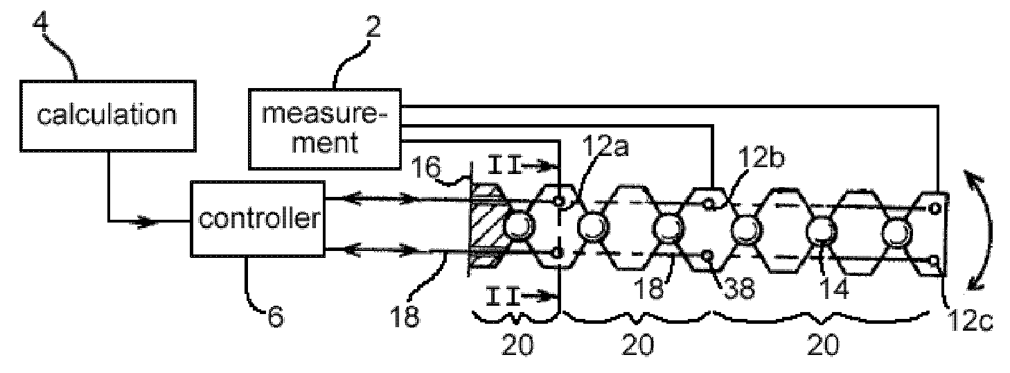
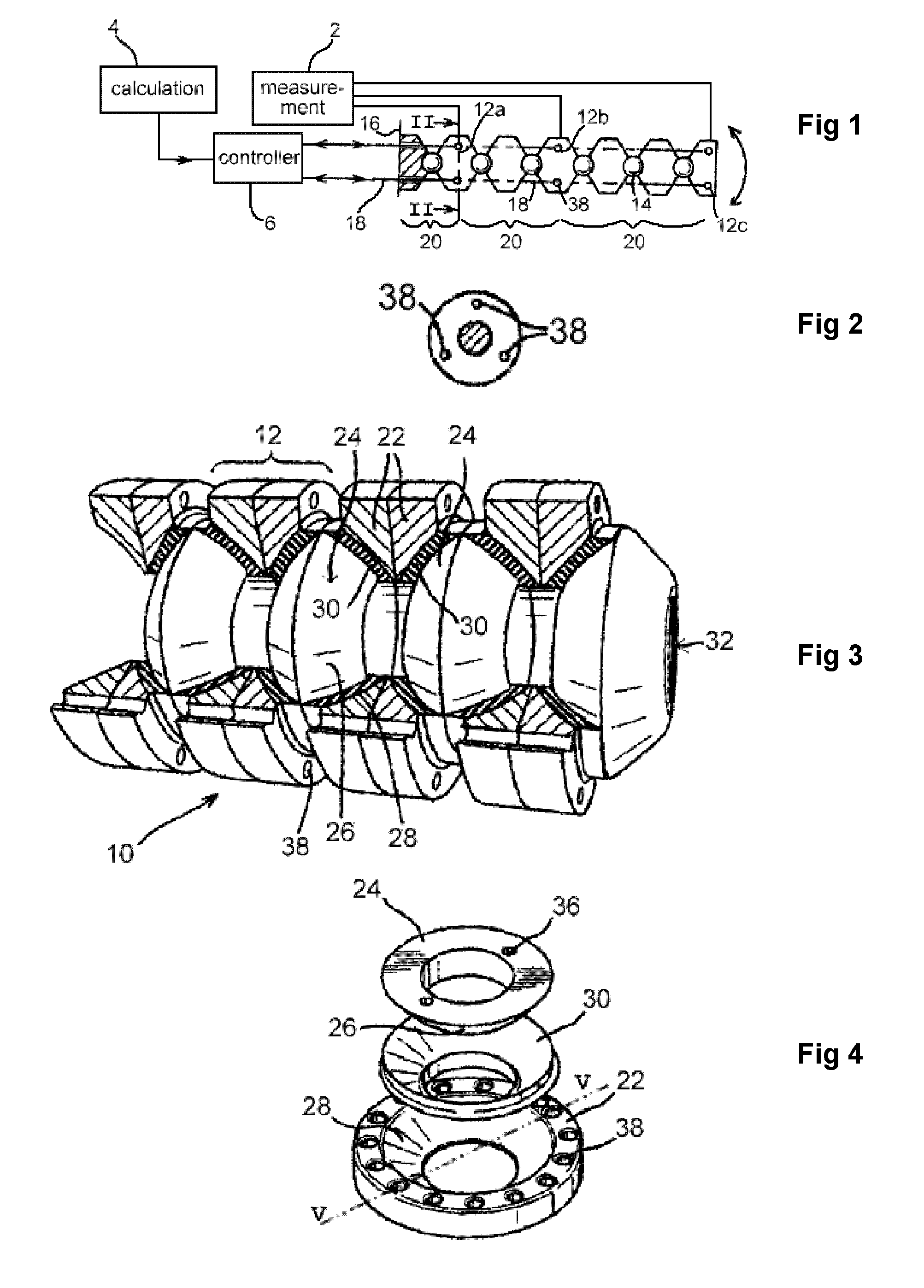
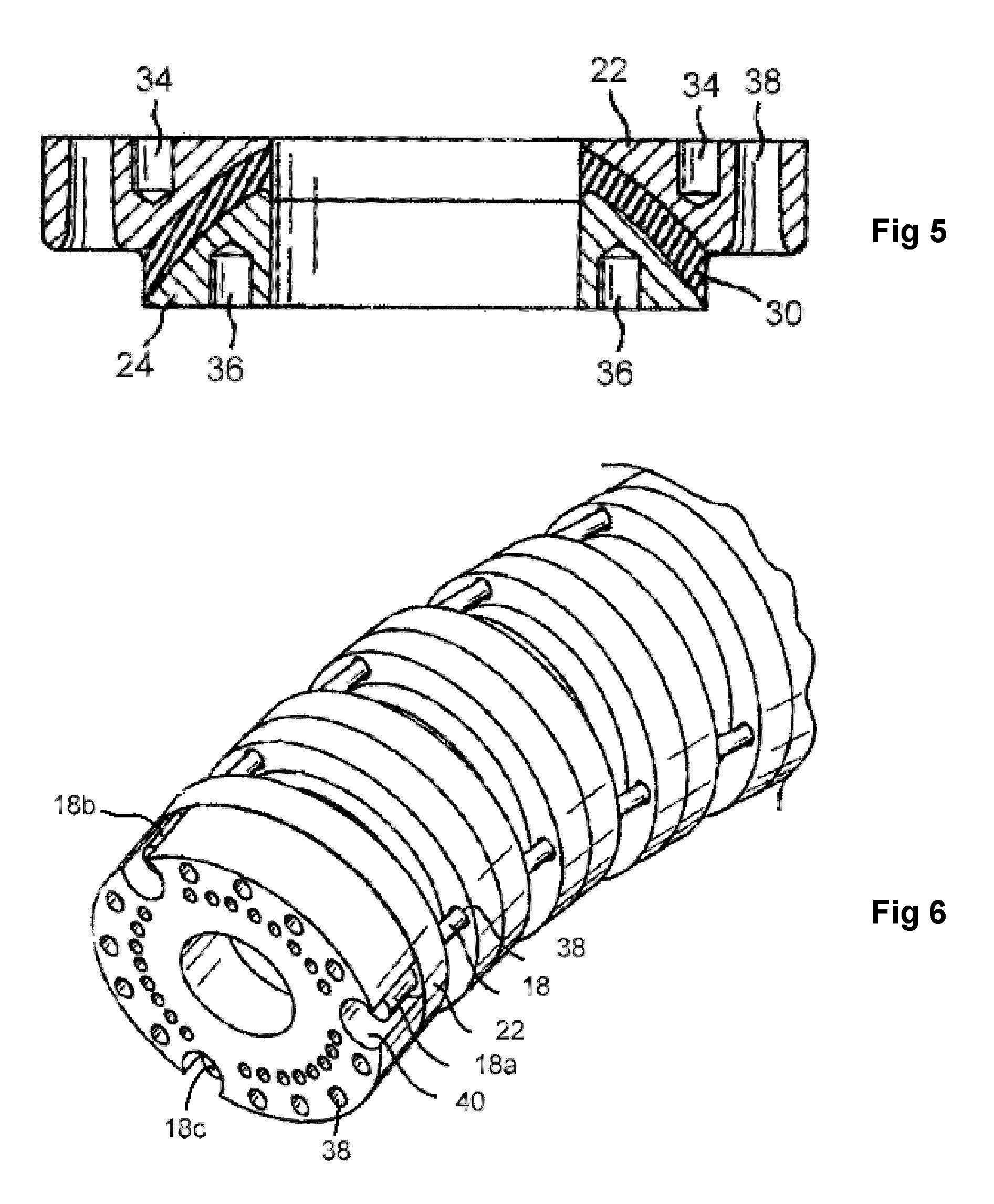
[0047]Referring to FIG. 1, a robotic arm 10 comprises a plurality of elements in the form of links 12 connected by articulated joints 14. The arm is mounted on a base plate 16 at the proximal end. A plurality of control wires 18 extend from a controller 6 through the base plate 16 and through apertures 38 in the periphery of each link 12. The control wires 18 are arranged into groups of three which are circumferentially spaced as shown in FIG. 2, each group terminating at a particular link 12a, 12b, or 12c along the arm by being bonded to the link. Where a group of wires terminates, this link is the control link, and defines the end of a segment 20. Movement of the group of control wires 18 by the controller controls the position of that particular control link 12a, 12b or 12c, and thus of the associated segment 20.

[0048]Measurement means 2 gather position data for example from the control link in each segment, as will be described above. Calculation means 4 is provided to process t...


PUM


Abstract

A robotic arm comprises a plurality of articulated elements, and control means for controlling the position of various of the elements such that the arm may adopt serpentine shape for tip following movement. Means for measuring directly the relative positions of at least some of the elements are provided in order to calculate deviation from the theoretical shape, and apply corrections to the arm control means.

Description

CROSS-REFERENCE TO RELATED APPLICATIONS[0001]The present application is a continuation of pending International patent application PCT / GB2006 / 02284 filed on Jun. 21, 2006 which designates the United States and claims priority from United Kingdom patent application 0512592.7 filed on Jun. 21, 2005, United Kingdom patent application 0512581.0 filed on Jun. 21, 2005 and United Kingdom patent application 0512583.6 filed on Jun. 21, 2005 the content of which is incorporated herein by reference.FIELD OF THE INVENTION[0002]This invention relates to robotic arms, and in particular to robotic arms having ‘tip following’ capability.BACKGROUND OF THE INVENTION[0003]In the field of robotics there has been considerable development of robotic arms having a tip following capability; that is to say, the arm is capable of advancing longitudinally of itself in a snakelike manner. Such arms can carry a workload or tool and can be used for inspection of equipment with restricted access, such as the int...

Claims


Application Information

Patent Timeline
IPC IPC(8): B25J13/08B25J19/02G01C3/00
CPCB25J9/06B25J18/06
Inventor BUCKINGHAM, ROBERT OLIVERGRAHAM, ANDREW CRISPIN
Owner OLIVER CRISPIN ROBOTICS
Why Eureka
Try Eureka