Antenna device and communication terminal

a technology of communication terminal and antenna device, which is applied in the direction of resonant antennas, elongated active elements, antenna supports/mountings, etc., can solve the problems of complex design, increased cost, and complex structure of antenna device components, and achieve the effect of favorable characteristics of the second frequency band

Inactive Publication Date: 2009-11-12
SNAPTRACK
View PDF14 Cites 50 Cited by
  • Summary
  • Abstract
  • Description
  • Claims
  • Application Information

AI Technical Summary

Benefits of technology

[0031]That is, the communication terminal according to the embodiment of the invention includes the above described antenna device according to the embodiment of the invention. Thus, with the communication terminal according to the emb...

Problems solved by technology

However, there is a problem that any of these antenna device components have a complex structure.
In addition, the antenna device suggested in Translation of PCT Application No. 2005-521315 uses an expensive high-dielectric material and, therefore, there is a problem that the cost increases.
Moreover, because the structure is complex, there is another problem that the design is complex.
In additio...

Method used


Image

  • Antenna device and communication terminal
  • Antenna device and communication terminal
  • Antenna device and communication terminal

Examples


first embodiment

[0069]A communication terminal according to a first embodiment of the invention and an antenna device component (antenna device) included in the communication terminal will be described with reference to FIG. 1 to FIG. 25B.

Configuration of Communication Terminal

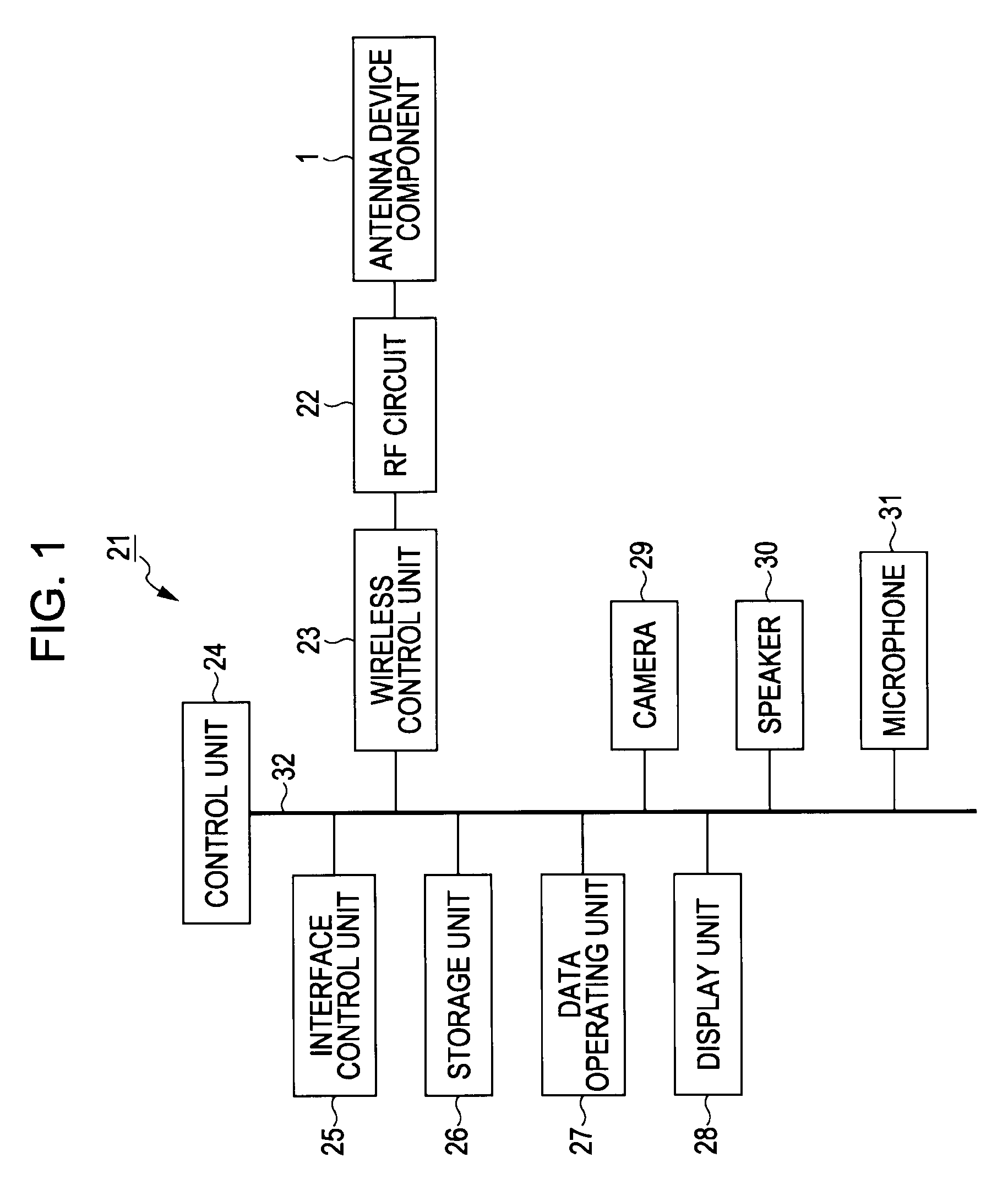
[0070]First, the configuration of the communication terminal according to the present embodiment will be described. Note that in the description of the present embodiment, a mobile communication terminal is used as the communication terminal as an example. However, the mobile communication terminal is a so-called cellular phone terminal and is a terminal that carries out wireless communication with a base station for wireless telephones. FIG. 1 shows the block configuration diagram of the mobile communication terminal equipped with the antenna device component 1 according to the present embodiment.

[0071]As shown in FIG. 1, the mobile communication terminal 21 includes the antenna device component 1, an RF (Radio Frequency) ci...

second embodiment

[0146]An example of an antenna device component according to a second embodiment of the invention will be described with reference to FIG. 26 to FIG. 28. In the second embodiment, the antenna device component that further improves matching in a high-frequency band as compared with that of the first embodiment will be described.

Configuration of Antenna Device Component

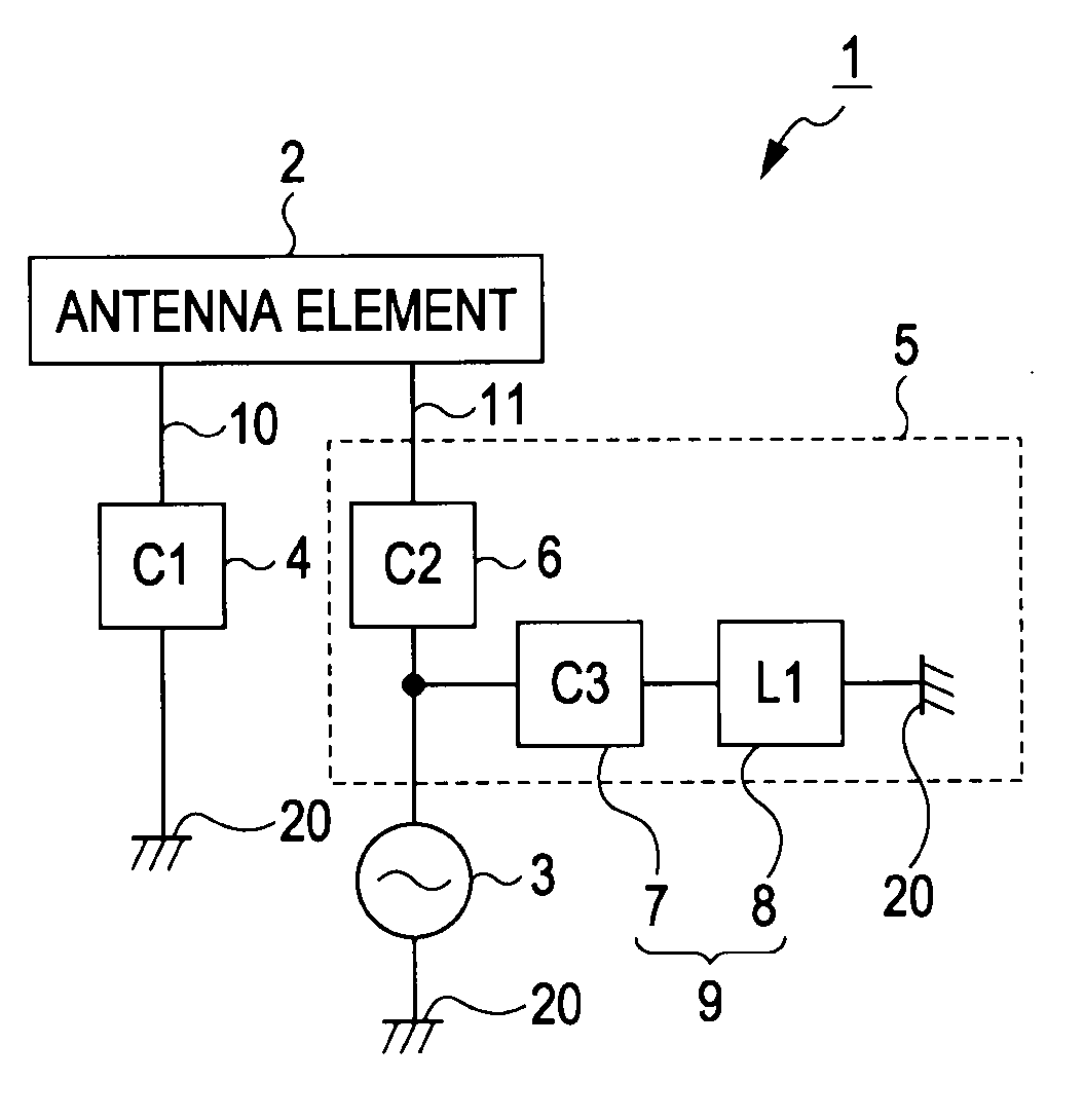
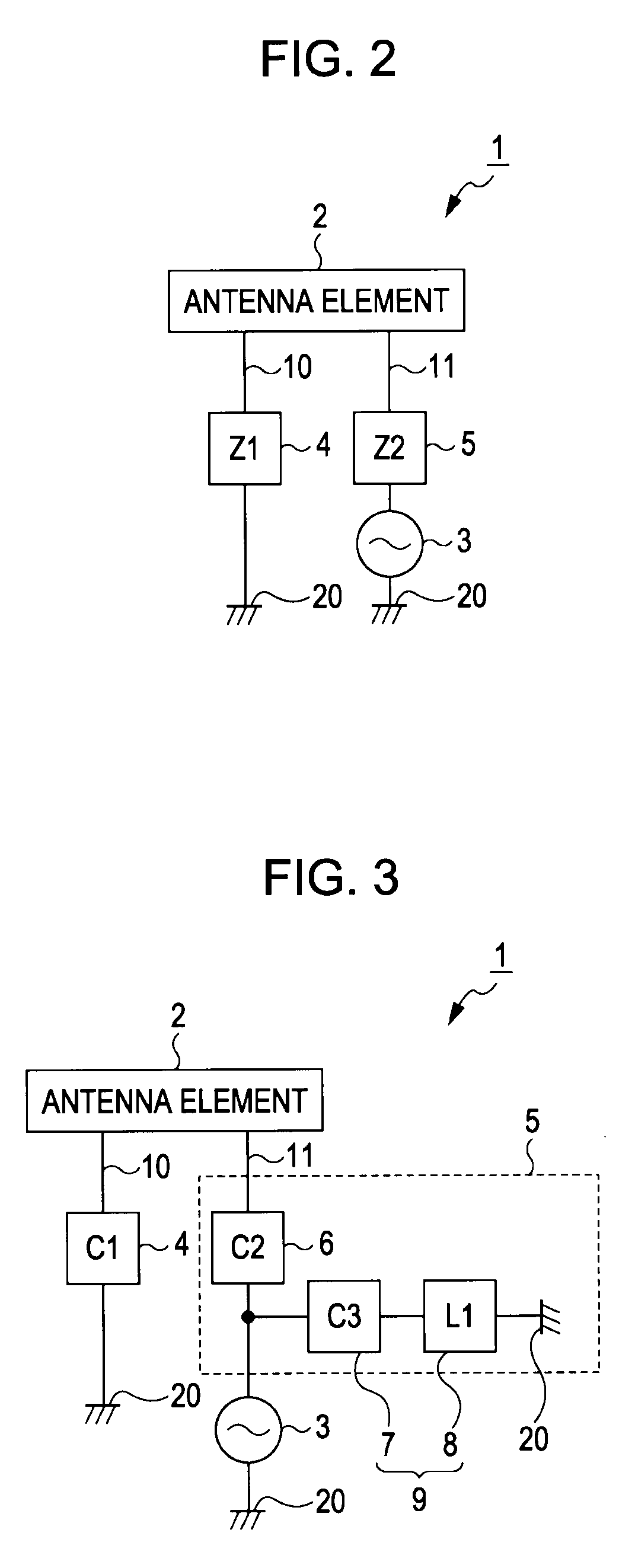
[0147]The schematic configuration of the antenna device component according to the present embodiment is shown in FIG. 26. Note that the antenna device component of the present embodiment is a single-feeder antenna device component with multiband capability. As shown in FIG. 26, the antenna device component 41 of the present embodiment includes an antenna element 2, a feeding point 3, a first bandwidth adjustment circuit 4 (first capacitor 4) and a second bandwidth adjustment circuit 45.

[0148]In the present embodiment, as is apparent from comparison between FIG. 26 and FIG. 3, the configuration of the second bandwidth a...

third embodiment

[0158]An example of an antenna device component according to a third embodiment of the invention will be specifically described with reference to FIG. 29 and FIG. 30.

[0159]In the antenna device component 1 of the first embodiment, the first capacitor 4 (first bandwidth adjustment circuit)and the second capacitor 6 and third capacitor 7 of the second bandwidth adjustment circuit 5 are substantially placed in a short-circuit state for signals in a high-frequency band. That is, the antenna device component 1 is configured so that the reactance of each of the first capacitor 4, the second capacitor 6 and the third capacitor 7 in a high-frequency band is extremely small and may be ignored. However, for example, as shown in FIG. 15, the reactance of the capacitor is not completely equal to 0 in a high-frequency band. Then, the inventors studied the influence of the reactance of the capacitor in a high-frequency band and found the following facts.

[0160]When, in the antenna device component...


PUM


Abstract

An antenna device includes: an antenna element that transmits or receives wireless signals in a predetermined first frequency band and in a second frequency band higher in frequency than the first frequency band; a feeding terminal portion; a first bandwidth adjustment circuit that includes a first capacitor for widening a bandwidth of the first frequency band to a predetermined bandwidth, the capacitance of the first capacitor being set at a predetermined value in accordance with the predetermined bandwidth; and a second bandwidth adjustment circuit that includes second and third capacitors and a first inductor for widening a bandwidth of the first frequency band to the predetermined bandwidth, the capacitance of each of the second and third capacitors and the inductance of the first inductor being respectively set at predetermined values in accordance with the predetermined bandwidth.

Description

BACKGROUND OF THE INVENTION[0001]1. Field of the Invention[0002]The invention relates to an antenna device and a communication terminal and, more particularly, to a single-feeder antenna device with multiband capability and a communication terminal equipped with the antenna device.[0003]2. Description of the Related Art[0004]In recent years, some cellular phones use GSM (Global System for Mobile Communications) as one of wireless communication systems. The available frequency band in the GSM is, for example, 850 MHz band, 900 MHz band, 1800 MHz band, 1900 MHz band, or the like. In addition, other than the GSM, a UMTS (Universal Mobile Telecommunication System) is employed as a wireless communication system, and the available frequency band of the UMTS is 2 GHz band.[0005]In addition, in an existing art, a wireless communication terminal, such as a cellular phone terminal, capable of handling the above described wireless communication systems has been developed. Such a wireless commu...

Claims


Application Information

Patent Timeline
IPC IPC(8): H01Q9/00H01Q1/50H01Q5/10H01Q5/328H01Q5/335H01Q5/371H01Q5/378H01Q9/42
CPCH01Q1/24H01Q23/00H01Q5/378H01Q5/335H01Q5/371H01Q5/328
Inventor SHOJI, HIDEAKI
Owner SNAPTRACK
Why Eureka
Try Eureka