Method of detecting discontinuities on elongated workpieces

a technology of discontinuities and workpieces, applied in the direction of analysing solids using ultrasonic/ultrasonic/infrasonic waves, processing detected response signals, etc., can solve the problems of destructive interference of uninterfered circulating waves at the site of the receiver, and suffer shortcomings, etc., to achieve the effect of complex structure of the reception signal

Inactive Publication Date: 2005-01-18
MANNESMANN ROHRENWERKE
View PDF7 Cites 54 Cited by
  • Summary
  • Abstract
  • Description
  • Claims
  • Application Information

AI Technical Summary

Benefits of technology

In general, the differential process according to the present invention is applicable for any type of generated reception signals. The advantage of the differential process according to the present invention is especially favorable when the structure of the reception signals is complicated. An example involves reflection indications by Lamb waves generated in the test object. This type of inspection, may be expanded by generating alternatively in the test clock cycle two wave pulses at two sites located in circumferential direction, with the wave pulses propagating in both circumferential directions. In this case, the differential process can be applied to both the reflected pulses and the attenuated pulses.

Problems solved by technology

The location of reception and the excitation of the wave pulses propagating simultaneously in both circumferential directions of the test object is selected such that both uninterfered circulating waves destructively interfere at the site of the receiver.
Both these conventional process suffer shortcomings because very short discontinuities, e.g. a hole, or discontinuities in unfavorable location may not be detected due to a low signal level.

Method used


Image

  • Method of detecting discontinuities on elongated workpieces
  • Method of detecting discontinuities on elongated workpieces
  • Method of detecting discontinuities on elongated workpieces

Examples


Embodiment Construction

Throughout all the Figures, same or corresponding elements are generally indicated by same reference numerals. These depicted embodiments are to be understood as illustrative of the invention and not as limiting in any way.

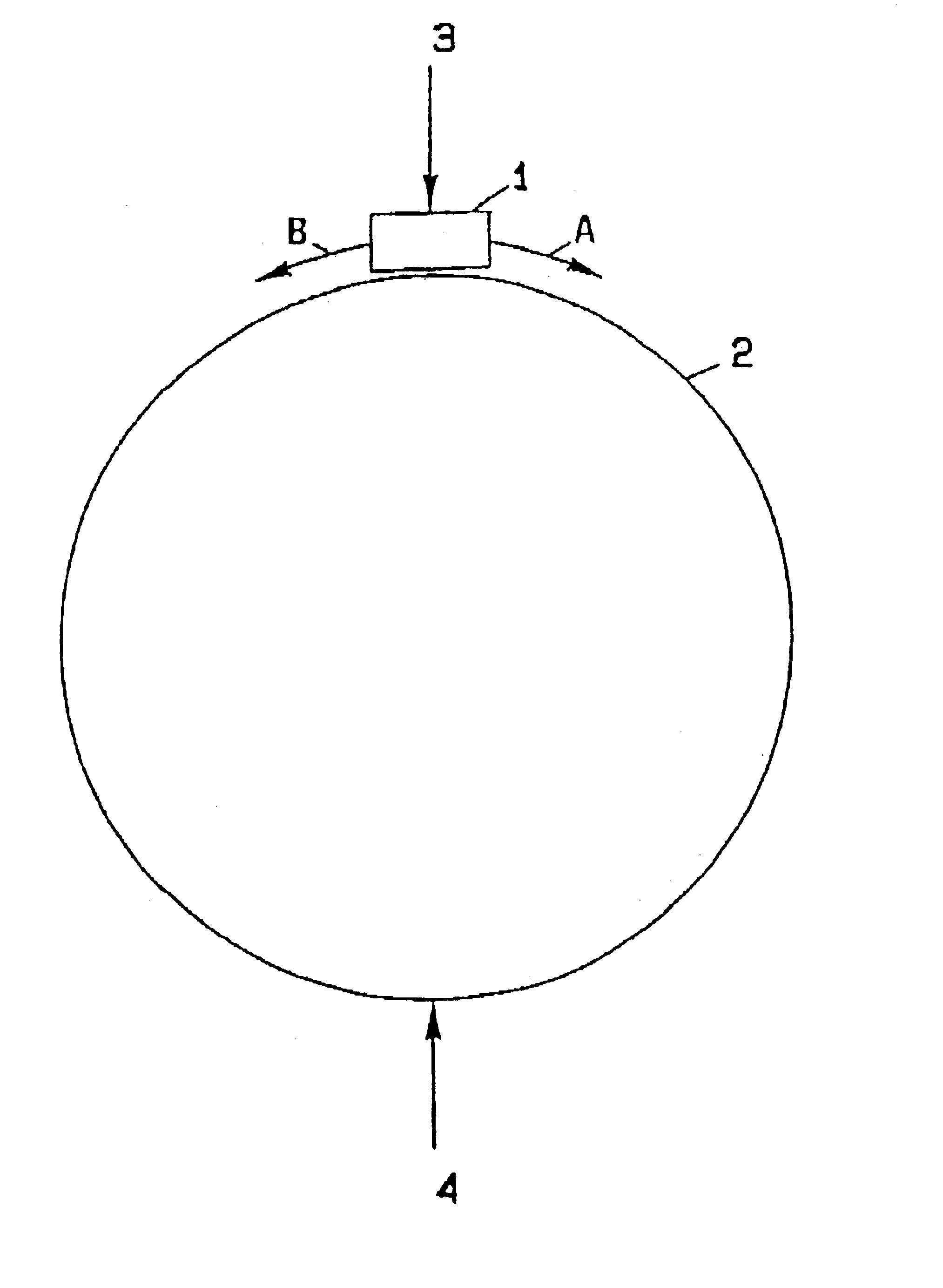
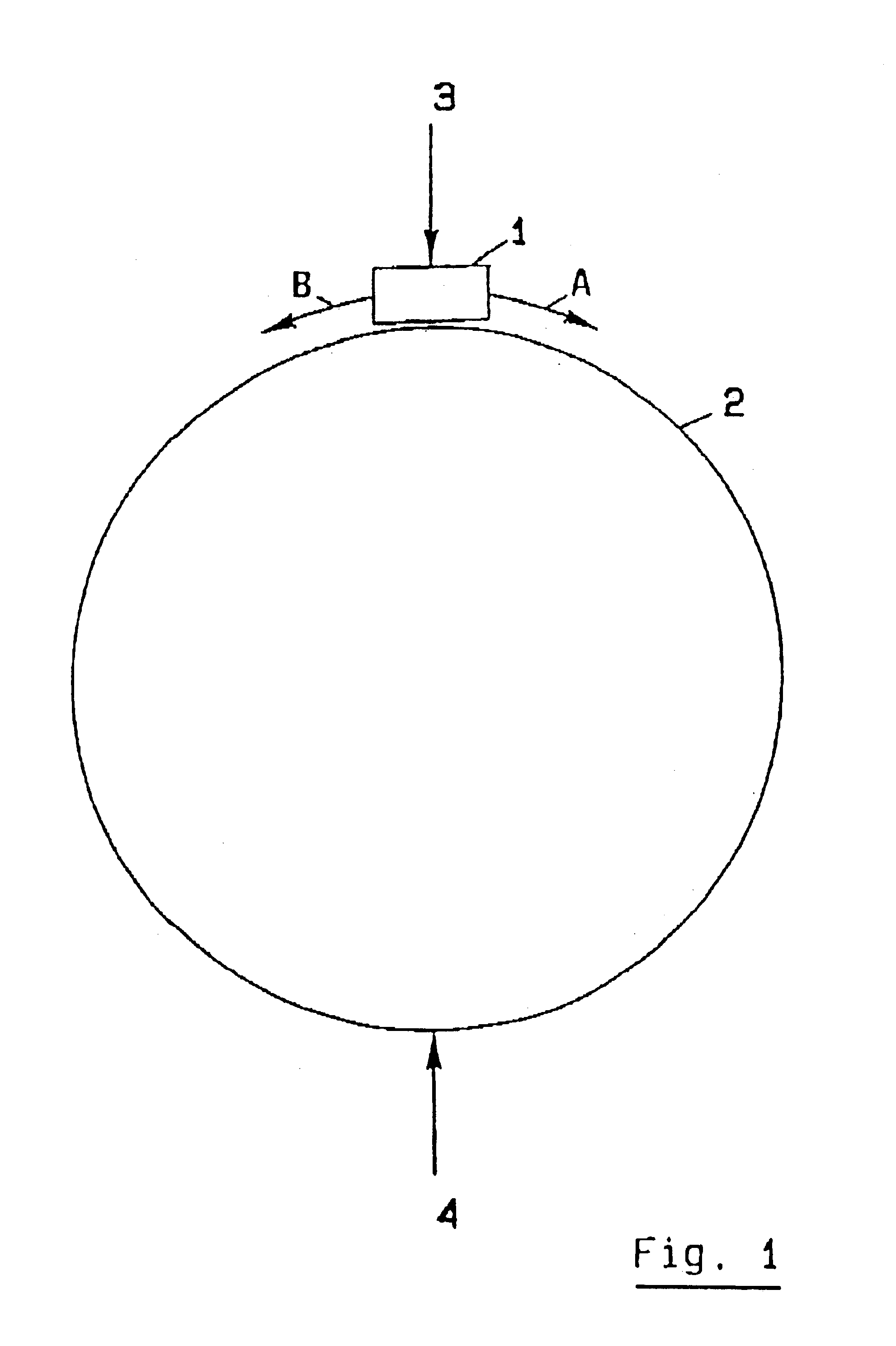
Turning now to the drawing, and in particular to FIG. 1, there is shown a basic diagram of a first exemplified embodiment for carrying out an evaluation process according to the present invention. A transducer 1 located at a certain distance from a test object 2 simultaneously emits a wave pulse A, B in both circumferential directions. In FIG. 1, the wave pulse emitted in the clockwise direction is designated by index A, and the wave pulse emitted in the counterclockwise direction is designated by index B. Both wave pulses A, B circulate several times in the circumferential direction and meet at two defined points of the circumference: once at the transducer 1 itself, here designated position 3, and on the side exactly opposite by 180°, here designated position 4....


PUM

PropertyMeasurementUnit
lengthaaaaaaaaaa
wavelengthaaaaaaaaaa
frequencyaaaaaaaaaa

Abstract

In a method of detecting discontinuities on elongated workpieces, in particular tubes and bars, using ultrasonic testing system, a test object is positioned in relationship to a test head of the testing system, with the test object and the test head being moveable to one another. Signals from the test head are transmitted to an evaluation unit, where they are digitized and evaluated. The digitized signals of a test shot of a length position X are compared with digitized signals of a test shot of a length position X+ΔX, wherein ΔX is a multiple of a shot distance, and the difference is evaluated.

Description

BACKGROUND OF THE INVENTIONThe present invention relates to a method of detecting discontinuities on elongated workpieces, in particular on tubes and bars, using ultrasound.German patent publication DE 36 22 500 A1 discloses a process and apparatus for the detection of discontinuities on cylindrical tubes and bars. Discontinuities are detected by moving the test object past stationary transmission and receiving transducers, which detect tangentially circulating guided wave pulses in the test object, whereby the amplitudes of the sequentially received signals are processed in a computer by forming a quotient to determine defects. The received signals are synchronized for evaluation with burst signals of the same frequency, a suitable time period and start delay, and transmitted to a peak detector. The amplitudes are digitized and transmitted to a computer.German patent publication DE 39 43 226 C2 discloses a process for the detection of discontinuities on elongated workpieces, in par...

Claims


Application Information

Patent Timeline
Patent Type & Authority Patents(United States)
IPC IPC(8): G01N29/26G01N29/11G01N29/34G01N29/275G01N29/04G01N29/44
CPCG01N29/11G01N29/275G01N29/343G01N29/4445G01N2291/2634G01N2291/011G01N2291/0423G01N2291/044
Inventor GRAFF, ALFREDSCHLAWNE, FRIEDHELM
Owner MANNESMANN ROHRENWERKE
Why Eureka
Try Eureka