Backrest-tilting device

a backrest and tilting technology, applied in the direction of chairs, movable seats, rocking chairs, etc., can solve the problems of increasing the number of parts, increasing the complexity of assembling, so as to achieve easy assembly, simple structure, and simple structure

Active Publication Date: 2010-06-01
OKAMURA CORP
View PDF9 Cites 56 Cited by
  • Summary
  • Abstract
  • Description
  • Claims
  • Application Information

AI Technical Summary

Benefits of technology

[0005]However, in such a device, the core in a plurality of force-promoting units comprising a rubber torsion spring is not the same as the shaft of the backrest support rod thereby increasing the number of parts, making the structure and assembling more complicate.
[0006]Especially, in JP2004-49717A, after a plurality of force-promoting units comprising a rubber torsion spring is received in the support, the hexagonal shaft is passed through the hexagonal hole of the core of the torsion spring from the side of the support. Thereafter, the ends of the beackrest support rods supporting the backrest have to be fixed to the ends of the shaft, thereby making assembling more complicate, especially, passing the hexagonal shaft through the hexagonal hole of the core of the rubber torsion spring and requiring a lot of time.
[0009]It is an object of the present invention to provide a backrest-tilting device in a reclining chair, the device being simple in structure and being able to be easily assembled.
[0010]It is another object of the present invention to provide a backrest-tilting device in a reclining chair, enabling the backrest to be held at an optional angle, the device being simple in structure and being able to be assembled for a short time.
[0011]It is further object of the present invention to provide a backrest-tilting device in a reclining chair, initial promoting force of the backrest being easily adjusted by turning an operating handle at the lower side of a seat even when a sitting person still sits on the seat, turning resistance of an operating shaft being not able to increase even if initial promoting force of the backrest becomes larger.
[0012]It is yet another object of the present invention to provide a backrest-tilting device in a reclining chair, a pivot of a backrest support rod that supports the backrest and force-promoting unit for the backrest being easily and surely assembled to the support for a short time.

Problems solved by technology

However, in such a device, the core in a plurality of force-promoting units comprising a rubber torsion spring is not the same as the shaft of the backrest support rod thereby increasing the number of parts, making the structure and assembling more complicate.
Thereafter, the ends of the beackrest support rods supporting the backrest have to be fixed to the ends of the shaft, thereby making assembling more complicate, especially, passing the hexagonal shaft through the hexagonal hole of the core of the rubber torsion spring and requiring a lot of time.
As promoting force becomes larger, turning resistance of the adjusting screw increases to make it more difficult to handle the screw.

Method used


Image

  • Backrest-tilting device
  • Backrest-tilting device
  • Backrest-tilting device

Examples


Embodiment Construction

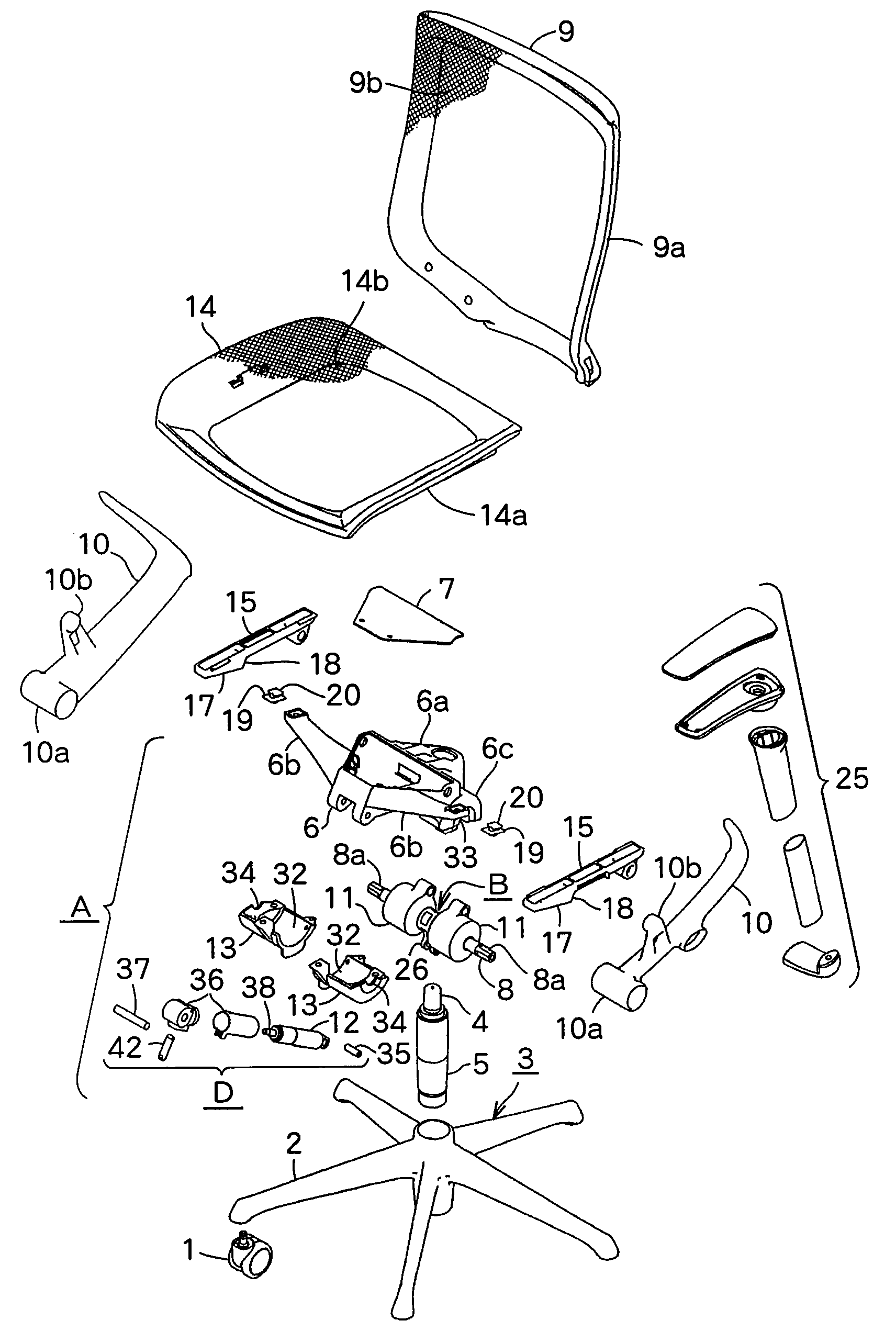
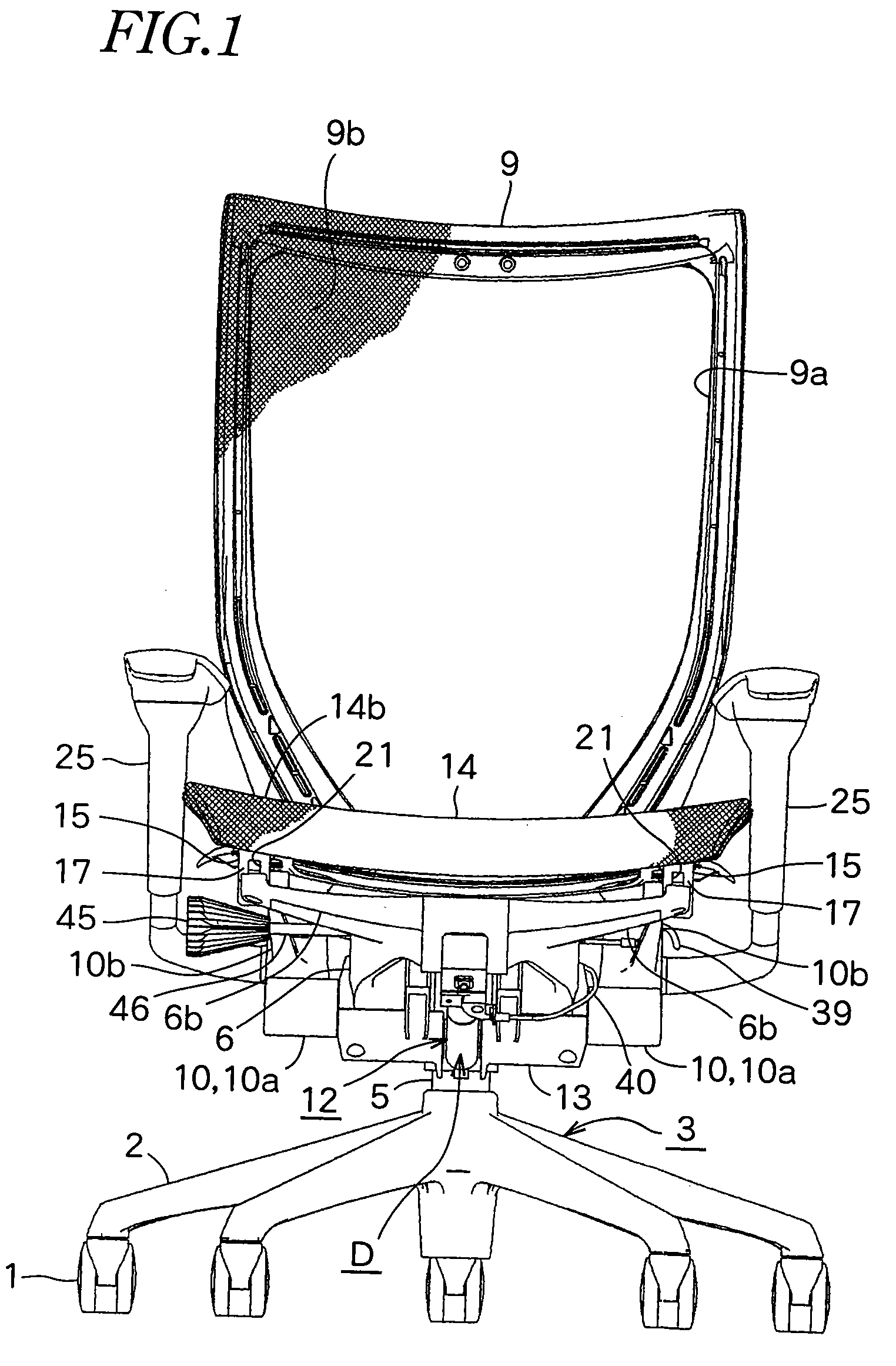
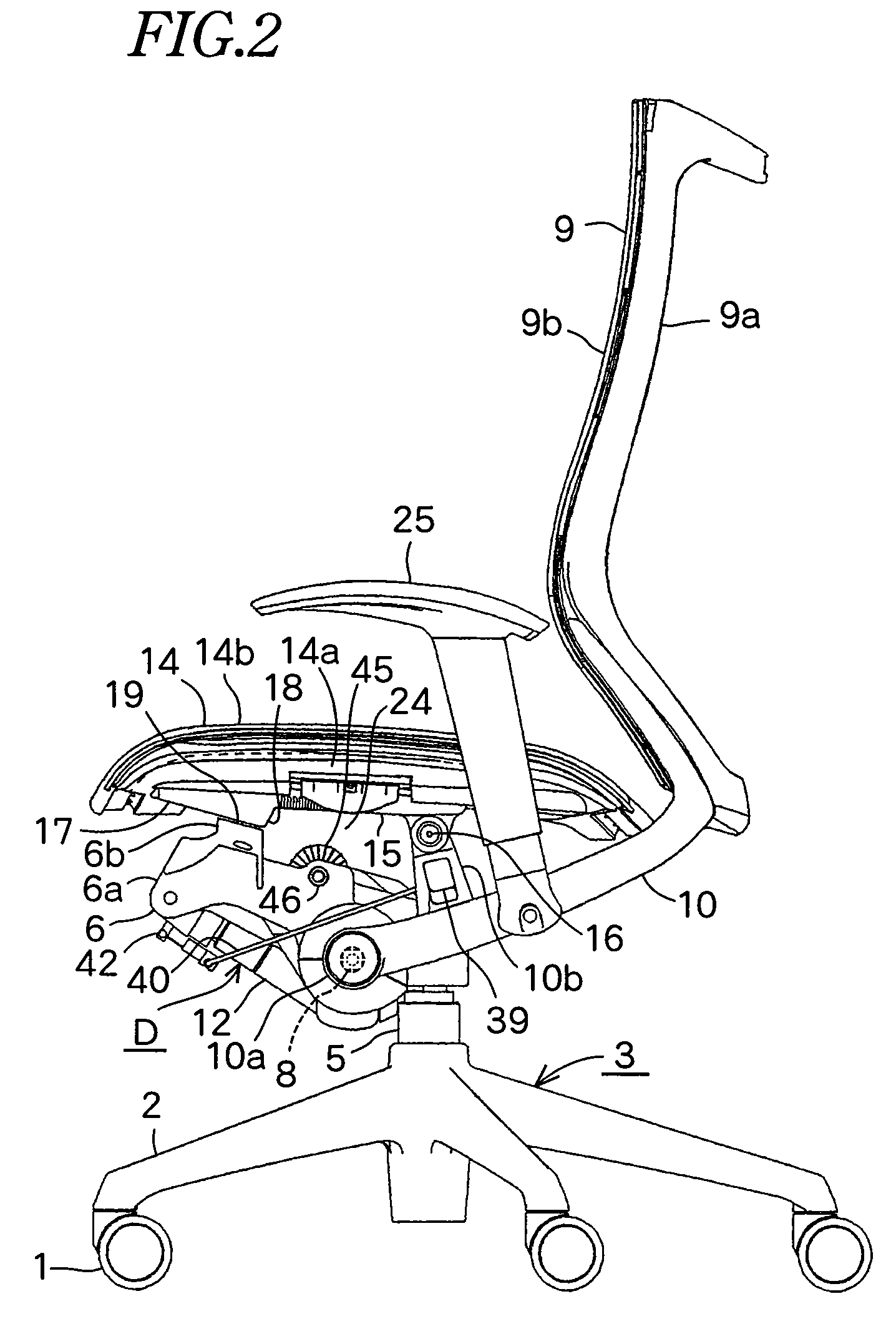
[0024]As shown in FIGS. 1-3, a reclining chair comprises a leg 3 having five leg rods 2 radially extending and having a caster 1 at the end. At the center of the leg 3, a telescopic post 5 having a gas spring 4 is provided, and a support 6 which supports a seat 14 is fixed at the upper end of the post 5.

[0025]The support 6 comprises a hollow rhombus-shaped support body 6a and a front-half upper opening is covered with an upper cover 7. A pair of arms 6b, 6b are mounted on each side of the support body 6a so that the upper surfaces of the ends of the arms 6b, 6b are disposed at a position higher than the support body 6a.

[0026]A pivot 8 which has a rectangular shaft portions 8a, 8a at each end passes through the middle of the support body 6a. A pair of backrest support rods 10,10 support the backrest 9 and have tubular portions 10a, 10a at the front respectively. Tubular portions 10a, 10a engage with the rectangular shaft portions 8a, 8a respectively thereby rotating the pivot 8, the...


PUM


Abstract

A back rest tilting device in a reclining chair formed of fewer parts. A force promoting unit energizes a back rest in an upright direction. A rotating force promoting unit with rubber torsion springs includes a laterally extending pivot shaft rotated integrally with the back rest and an elastic body filled between an outer tube locked to a support body coaxially with the core and the pivot shaft so that the elastic body is elastically deformed when the pivot shaft is rotated about the center axis of the outer tube to impart a returning rotating force to the pivot shaft.

Description

CROSS REFERENCE TO RELATED APPLICATIONS[0001]The present application is a 35 U.S.C. §371 national phase conversion of PCT / JP2005 / 017354 filed Sep. 21, 2005, which claims priority of Japanese Application No. 2004-275877 filed Sep. 22, 2004, Japanese Application No. 2004-275878 filed Sep. 22, 2004, Japanese Application No. 2004-275879 filed Sep. 22, 2004 and Japanese Application No. 2004-275880 filed Sep. 22, 2004, the disclosures of which is herein incorporated by reference. The PCT Application was published in the Japanese Language.[0002]JP2004-49717A discloses that a rubber torsion spring is used as force-promoting unit for forcing the backrest to an upright position.[0003]In the device, a hexagonal shaft is pivotally supported through a support supported by a leg and each end of the shaft is fixed to a pair of backrest support rods supporting the backrest. A force-promoting unit for forcing the backrest towards an upright position comprises a core having a hexagonal hole through w...

Claims


Application Information

Patent Timeline
Patent Type & Authority Patents(United States)
IPC IPC(8): A47C1/024A47C3/026A47C7/40
CPCA47C1/03255A47C1/03261A47C1/03288A47C1/03283A47C1/03266A47C1/03294
Inventor MASUNAGA, HIROSHI
Owner OKAMURA CORP
Why Eureka
Try Eureka