
Punched-card machine placing base

A technology for placing bases and punching machines, which is applied in the direction of supporting machines, mechanical equipment, machine tables/supports, etc., can solve the problems of inconvenient fingerprint collection, and achieve the effects of convenient fingerprint identification, adjustment, and angle realization

Inactive Publication Date: 2018-11-30
成都朝立企业管理咨询有限责任公司
View PDF0 Cites 2 Cited by
  • Summary
  • Abstract
  • Description
  • Claims
  • Application Information

AI Technical Summary

Problems solved by technology

[0002] The company's human resources need to assess the attendance of employees, which requires the use of time cards. Generally, companies use fingerprint time card machines, but the current time card machines are placed directly on the desktop or assembled on the wall. The angle of the punch card machine is limited, so that it is not convenient for fingerprint collection

Method used


Image

  • Punched-card machine placing base

Examples


Embodiment Construction

[0010] The embodiments of the present invention will be further described below in conjunction with the accompanying drawings.

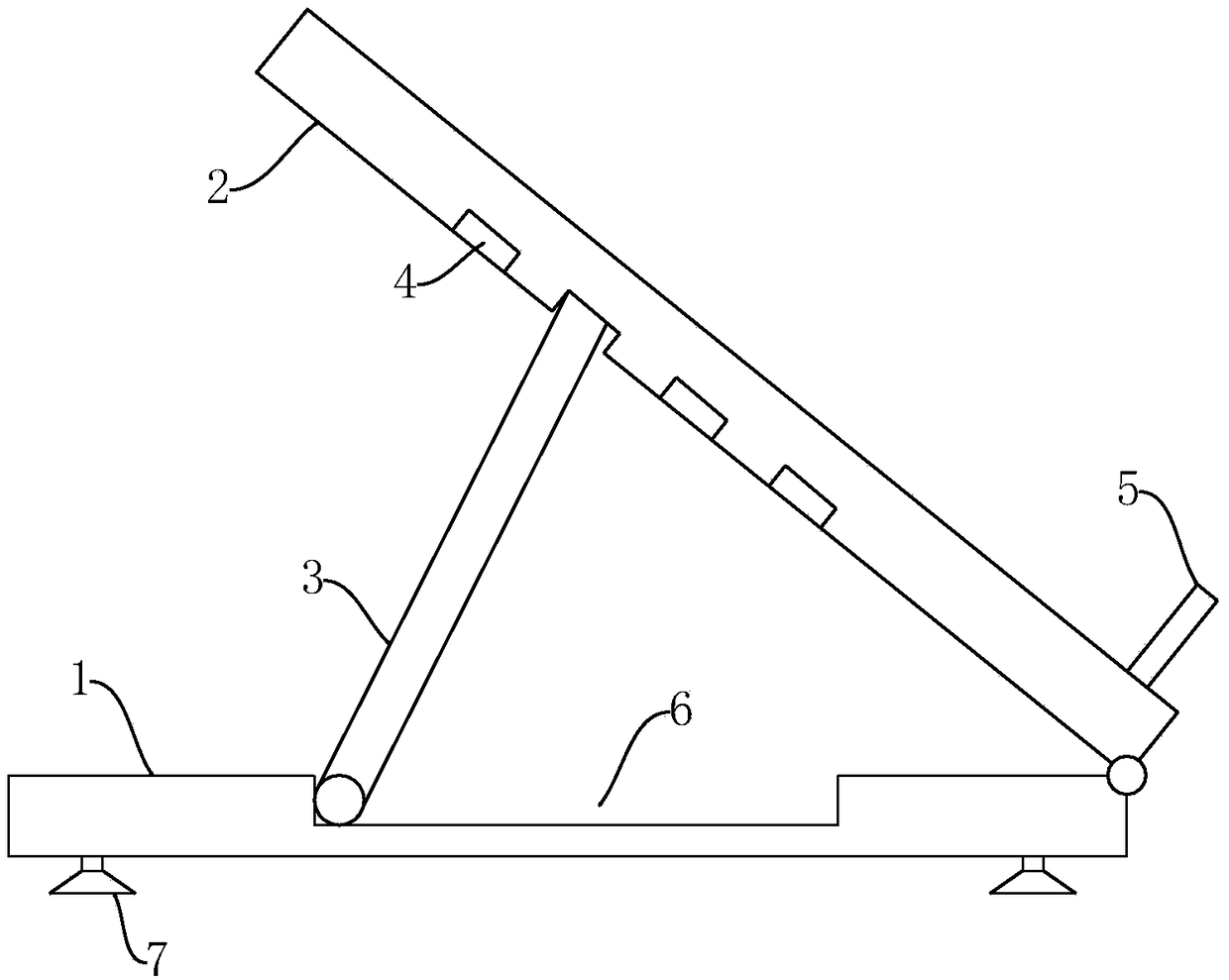
[0011] Such as figure 1 As shown, a card punching machine placement base provided by this embodiment includes a base plate 1, a support plate 2 is provided on the base plate 1, and the support plate 2 is rotatably connected with the base plate 1, and a support rod is provided on the base plate 1. 3. The support rod 3 is rotatably connected to the bottom plate 1, and the back of the support plate 2 is provided with a plurality of sockets 4 at intervals, so that the support rod 3 is rotated, and the top of the support rod 3 is inserted into different sockets 4. The adjustment of the angle of the support plate 2 is realized. In order to complete the storage of the support rod 3 when not in use, a placement groove 6 for receiving the support rod 3 may be provided on the bottom plate 1 .

[0012] The bottom of the front of the support plate 2 is provide...


PUM


Abstract

The invention relates to a punched-card machine placing base. The punched-card machine placing base comprises a baseplate, wherein a supporting plate is arranged on the baseplate and is rotatably connected to the baseplate; a supporting rod is arranged on the baseplate and is rotatably connected to the baseplate; multiple inserting openings are formed in the back of the supporting plate at intervals; and a supporting strip is arranged at the bottom of the front of the supporting plate. When the punched-card machine placing base is used, a punched-card machine is directly placed on the supporting plate; the adjustment of the angle of the supporting plate can be realized by adjusting the rotation angle of the supporting rod, thus, the adjustment of the angle of the punched-card machine is realized, and the identification of fingerprints on punched cards and the punched-card machine is facilitated.

Description

technical field [0001] The invention specifically relates to a card punching machine placement base. Background technique [0002] The company's human resources need to assess the attendance of employees, which requires the use of time cards. Generally, companies use fingerprint time card machines, but the current time card machines are placed directly on the desktop or assembled on the wall. The angle of the punch card machine is limited, which is not convenient for fingerprint collection. Contents of the invention [0003] In order to solve the above-mentioned technical problems, the object of the present invention is to provide a card punching machine placement base with convenient angle adjustment. [0004] The technical scheme adopted in the present invention is: a base for placing cards, including a base plate, a support plate is provided on the base plate, the support plate is rotatably connected with the base plate, a support rod is provided on the base plate, and...

Claims


Application Information

Patent Timeline
Patent Type & Authority Applications(China)
IPC IPC(8): F16M11/10F16M11/38
CPCF16M11/10F16M11/38
Inventor 胡伟
Owner 成都朝立企业管理咨询有限责任公司
Learn More