Movable gripper insulating rod

A technology of gripping rods and movable clips, applied in the direction of contact operating parts, etc., can solve problems such as poor operation, and achieve the effect of convenient operation and simple structure

Pending Publication Date: 2018-11-30
XIANNING POWER SUPPLY COMPANY OF STATE GRID HUBEIELECTRIC POWER
View PDF9 Cites 2 Cited by
  • Summary
  • Abstract
  • Description
  • Claims
  • Application Information

AI Technical Summary

Problems solved by technology

[0003] At present, the working head and the insulating rod of the ke rod are generally set straight, but there is a certain angle between opening and closing when people operate on the ground, so it is not easy to operate when operating the rules.

Method used


Image

  • Movable gripper insulating rod
  • Movable gripper insulating rod
  • Movable gripper insulating rod

Examples


Embodiment Construction

[0020] In order to make the technical means, creative features, goals and effects achieved by the present invention easy to understand, the following will further explain how the present invention is implemented in conjunction with the accompanying drawings and specific implementation methods.

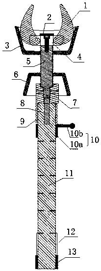
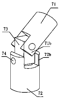
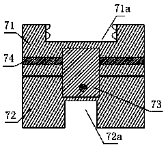
[0021] Such as figure 1 , figure 2 and image 3 As shown, the present invention provides a movable grip wand, comprising a work piece, a movable joint and an insulating rod 11, the work piece comprises a movable clamp 1, a support wire 2 and a tightness adjuster 3; the movable joint comprises a rotating cover 6 and universal joint 7;

[0022] The movable clip 1 is pin-shaft connected with the movable clip fixed foot 4, the supporting steel wire 2 is arranged on the upper end of the movable clip fixed foot 4, the lower end of the movable clip fixed foot 4 is fixedly connected with the upper end of the universal joint screw rod 5, and the tension adjuster 3 The inner wall is attached...


PUM


Abstract

The invention relates to a movable gripper insulating rod. The movable gripper insulating rod comprises a working piece, a movable connecting piece and an insulating rod, wherein the working piece comprises a movable clamp, a supporting steel wire and an elastic adjuster; the movable connecting piece comprises a rotating cover and a universal joint; one end of the movable clamp is in pin-shaft connection with the upper part of a movable clamp fixed foot; the supporting steel wire is arranged at the upper end of the movable clamp fixed foot; the lower end of the movable clamp fixed foot is fixedly connected with the upper end of a universal joint screw rod; the inner wall of the elastic adjuster is attached to the outer wall of the movable clamp, and the bottom of the elastic adjuster is inthreaded connection with the upper part of the universal joint screw rod; the lower part of the universal joint screw rod penetrates through the rotary cover to be in threaded connection with the upper end of the universal joint; and the lower end of the universal joint is fixed on the insulating rod through a universal shaft rod. The movable gripper insulating rod is simple in structure, and thework piece and the insulating rod are connected through the universal joint, so that a certain included angle is formed when people operate on the ground during opening and closing; and the rotatingrange of the universal joint is limited through the rotating cover, so that the movable gripper insulating rod is convenient to operate.

Description

technical field [0001] The invention relates to the field of operating tools for live work in power transmission and distribution lines of electric power systems, in particular to a movable gripper. Background technique [0002] The gram stick, also known as the brake lever, the operating lever, etc., is composed of three parts: the working head, the insulating rod and the handle. The gram rod is an insulating tool for operating live equipment in a short period of time, such as closing or opening a high-voltage isolating switch, pulling a line high-voltage load switch, pulling a drop fuse, installing and disassembling a portable ground wire, measuring and used during testing. The rod has good mechanical and electrical properties and insulation properties, and is one of the indispensable operating tools for live work on power transmission and distribution lines in power systems. [0003] At present, the working head and insulating rod of the ke rod are generally set straigh...

Claims


Application Information

Patent Timeline
Patent Type & Authority Applications(China)
IPC IPC(8): H01H3/02
CPCH01H3/02
Inventor 余磊
Owner XIANNING POWER SUPPLY COMPANY OF STATE GRID HUBEIELECTRIC POWER
Why Eureka
Try Eureka