A flexible rack

A kind of rack and flexible technology, applied in the direction of elements with teeth, belts/chains/gears, hoisting devices, etc., can solve the problems of narrow application range of a single specification rack, high cost, and the rack can no longer be used. , to achieve the effect of ingenious structure, convenient assembly and strong practicability

Active Publication Date: 2021-06-25
CHANGZHOU COLLEGE OF INFORMATION TECH
View PDF7 Cites 0 Cited by
  • Summary
  • Abstract
  • Description
  • Claims
  • Application Information

AI Technical Summary

Problems solved by technology

At present, the existing racks are rich in specifications, but the application range of a single rack is narrow. In the same transmission system, if the transmission system is improved, the specifications of the rack may no longer be applicable, so it is necessary to repurchase matching specifications. The rack is expensive, and the flexible rack ring also has this application disadvantage in the transmission system

Method used


Image

  • A flexible rack
  • A flexible rack
  • A flexible rack

Examples


Embodiment 1

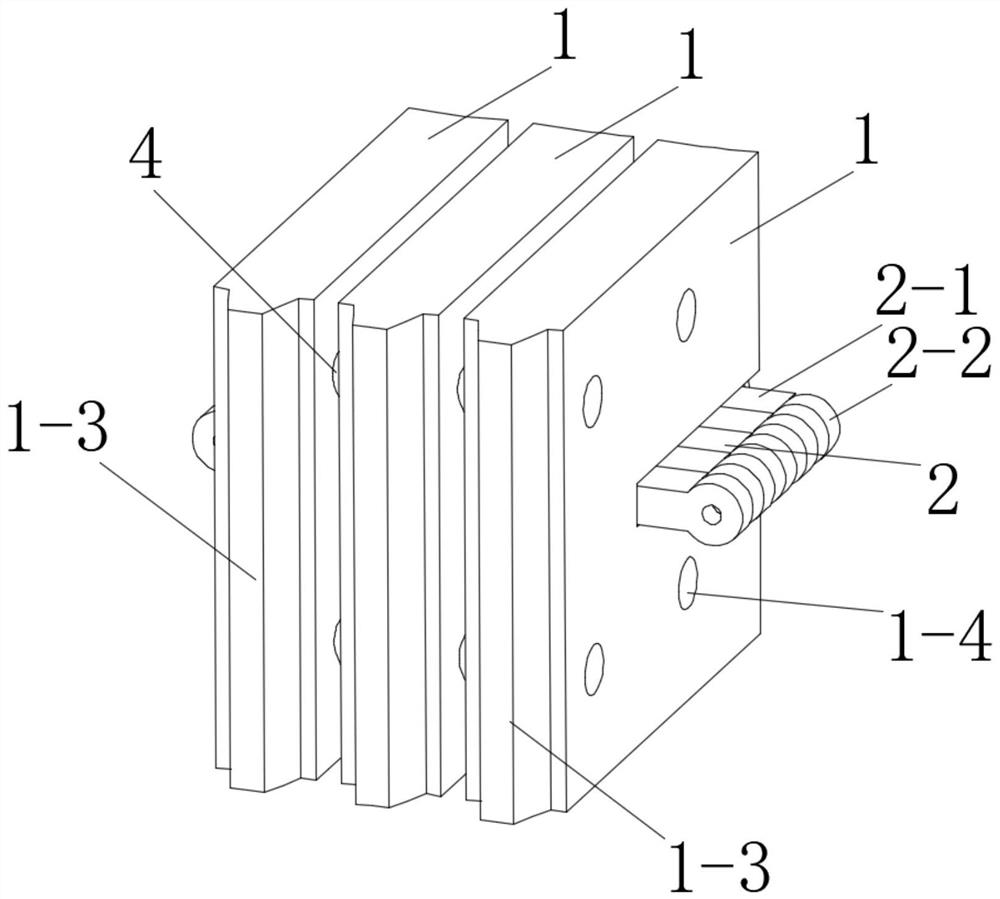
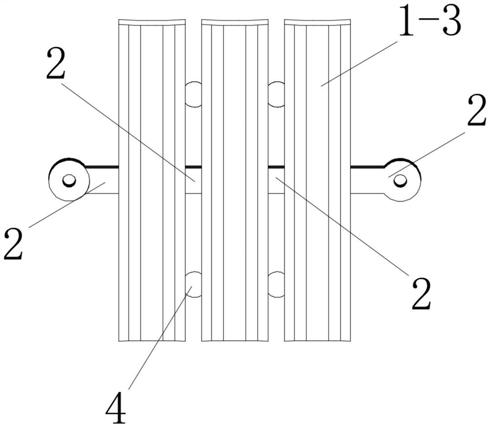
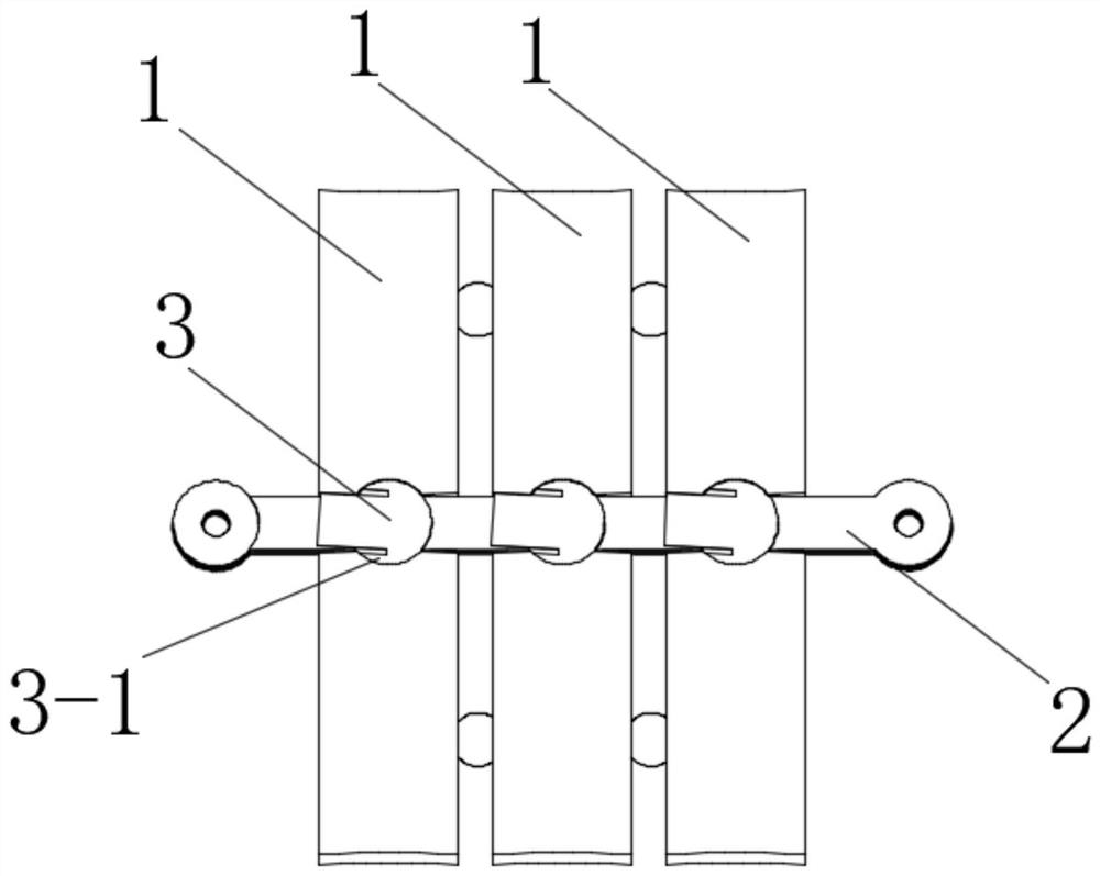
[0045] See Figure 1 to Figure 7 , the flexible rack of this embodiment includes a tooth body 1 and a tooth body connection assembly 2 . Both the tooth body 1 and the tooth body connecting assembly 2 are provided in plurality. Each tooth body 1 is arranged in sequence. Both sides of each tooth body connecting assembly 2 are respectively rotatably connected in the limiting spaces of two adjacent tooth bodies 1 . A stop piece 3 is provided in the limiting space of the tooth body 1 to prevent the tooth body connection assembly 2 from leaving the limiting space.

[0046] In order to cooperate more stably with the tooth body connection components, the limit effect is excellent, and the overall stability after assembly is improved, the limit space of the tooth body 1 includes the blind hole 1-1 on the back of the tooth body 1, and the On both sides of the body 1, and communicate with the notch 1-2 of the blind hole 1-1.

[0047] In order to provide a rotating space for the tooth...

Embodiment 2

[0062] See Figure 8 , this embodiment is basically the same as Embodiment 1, the difference is:

[0063] The tooth connection assembly 2 includes a second connection block 2-3. Both sides of the second connecting block 2-3 are provided with a plurality of second connecting rings 2-4 that fit into the limiting space of the tooth body 1, and the second connecting rings located on the same side of the second connecting block 2-3 2-4 are coaxial settings.

[0064] The second connection rings 2-4 on one side of the second connection block 2-3 of the tooth body connection assembly 2 and the second connection rings 2-4 on the other side are arranged alternately on the projection of the horizontal plane.

[0065] installation method:

[0066] Step 1: first connect two adjacent tooth body connection assemblies 2 by plugging, and the second connection rings 2-4 of the two tooth body connection assemblies 2 are coaxial to form corresponding connection shafts.

[0067] Step 2: Insert...

Embodiment 3

[0069] See figure 1 and figure 2 , the remainder of this embodiment is the same as in Embodiment 1, the difference being:

[0070] In order to provide elasticity between two adjacent tooth bodies and improve overall flexibility, a number of positioning balls 4 with elastic distances are arranged between every two adjacent tooth bodies 1 . Elastic pitch positioning ball 4 is made of rubber. Preferably, there are four elastic spacing positioning balls 4 arranged in a square shape.

[0071] In order to stably install the positioning balls 4 with elastic spacing, a plurality of spherical grooves 1-4 cooperating with the positioning balls 4 at elastic spacings are evenly distributed on both sides of the tooth body 1 .

[0072] To prevent the elastic distance positioning ball 4 from falling, the distance between every two adjacent tooth bodies 1 is smaller than the diameter of the elastic distance positioning ball 4 .


PUM


Abstract

The invention discloses a flexible rack, which includes a tooth body, a tooth body connection assembly and a stop piece; there are multiple tooth bodies and tooth body connection assemblies; each tooth body is arranged in sequence; the The two sides of each tooth body connection assembly are respectively movably connected in the limiting space of two adjacent tooth bodies; the limiting space of the tooth body is provided with a stop that restricts the tooth body connection assembly from breaking away from the limiting space piece. The present invention has an ingenious structure, which is an assembled structure as a whole. It is assembled by tooth body connecting components and tooth bodies. Low cost, stable structure, not only has the function of a conventional rack, but also can connect the two ends of the flexible rack end to end to form a flexible rack belt ring, so as to realize the transmission of multiple non-parallel transmission shafts at a long distance and in places where electricity is not suitable Synchronous mechanical transmission.

Description

technical field [0001] The invention relates to a flexible rack. Background technique [0002] The rack is a transmission part used for mechanical transmission. The types of racks now mainly include straight racks and flexible racks. At present, there are many specifications of racks, but the application range of a single rack is narrow. In the same transmission system, if the transmission system is improved, the specifications of the rack may no longer be applicable, so it is necessary to repurchase matching specifications. The rack is expensive, and the flexible rack ring also has this application disadvantage in the transmission system. Therefore, it is necessary to provide an assembled flexible rack that can be applied to synchronous mechanical transmission of multiple non-parallel transmission shafts over a long distance and where electricity is not suitable. Contents of the invention [0003] The purpose of the present invention is to provide an assembled flexible ...

Claims


Application Information

Patent Timeline
Patent Type & Authority Patents(China)
IPC IPC(8): F16H55/26
CPCF16H55/26
Inventor 刘光新刘军华孙磊厚颜鹏
Owner CHANGZHOU COLLEGE OF INFORMATION TECH
Why Eureka
Try Eureka