A multi-shaft synchronous transmission device for non-parallel shaft transmission

A multi-axis synchronization and transmission technology, which is applied in the direction of transmission, belt/chain/gear, mechanical equipment, etc., can solve problems such as the inability to apply multi-point transmission alone, large space production costs, and only one-to-one transmission. Achieve the effect of ingenious structure, less space occupation and smooth movement

Active Publication Date: 2021-03-23
CHANGZHOU COLLEGE OF INFORMATION TECH
View PDF6 Cites 0 Cited by
  • Summary
  • Abstract
  • Description
  • Claims
  • Application Information

AI Technical Summary

Problems solved by technology

At present, the existing drive shaft transmission devices usually adopt two transmission modes: parallel axis transmission and vertical axis transmission; the parallel axis transmission method has a large transmission space, and can only be one-to-one transmission, which occupies a large space and production costs; The vertical axis transmission is usually driven by the cooperation of gears and transmission shafts. The input part and the output part are in a vertical position relationship. The vertical axis transmission cannot be applied to multi-point transmission alone, and multiple vertical axis transmission devices are required for transmission separately. Multiple motors are required to drive, the production cost is high, and it takes up a lot of space

Method used


Image

  • A multi-shaft synchronous transmission device for non-parallel shaft transmission
  • A multi-shaft synchronous transmission device for non-parallel shaft transmission
  • A multi-shaft synchronous transmission device for non-parallel shaft transmission

Examples


Embodiment 1

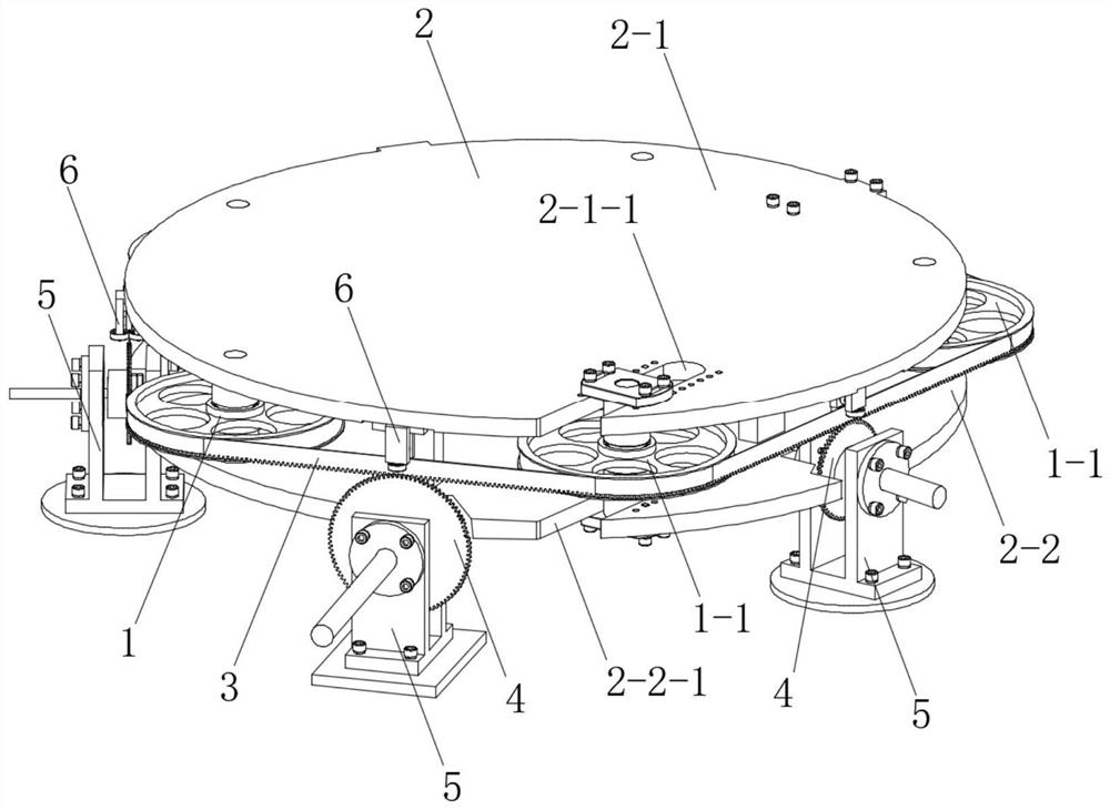
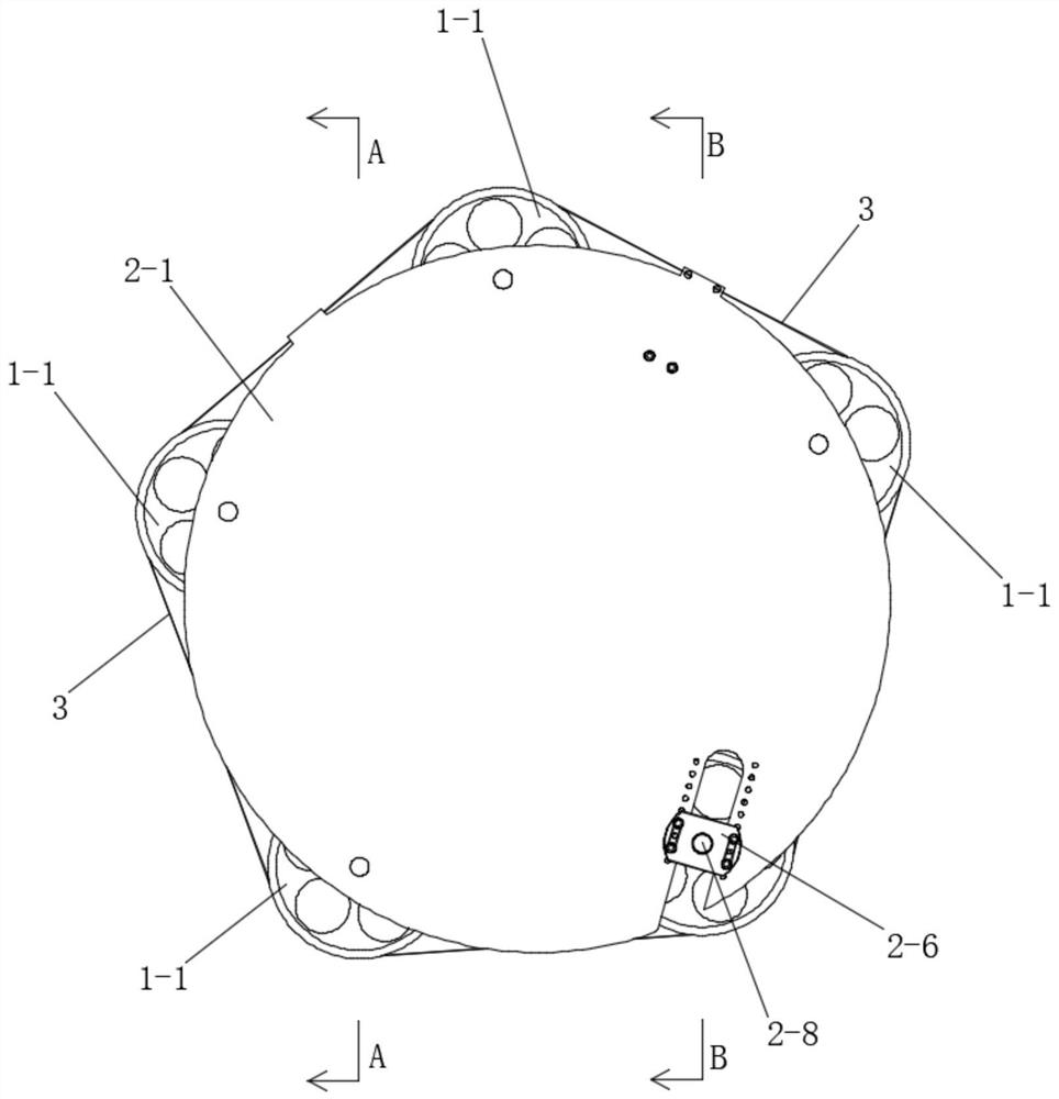
[0034] See Figure 1 to Figure 6 , the multi-axis synchronous transmission device for non-parallel shaft transmission in this embodiment includes a transmission wheel assembly 1 , a transmission wheel mounting base 2 , a flexible rack ring 3 , a pinion shaft assembly 4 and a base 5 . The transmission wheel assembly 1 is arranged on the transmission wheel mounting base 2 . The transmission wheel assembly 1 includes a plurality of transmission wheels 1 - 1 supporting the flexible rack ring 3 from the inside of the flexible rack ring 3 and cooperating with the flexible rack ring 3 . The bottom of the flexible rack ring 3 is provided with teeth. A plurality of bases 5 are evenly distributed along the bottom edge of the transmission wheel mounting base 2 . There are multiple gear shaft assemblies 4 and they are mounted on multiple bases 5 respectively. The pinion shaft assembly 4 meshes with the flexible rack gear 3 .

[0035] A plurality of transmission wheels 1-1 of the trans...

Embodiment 2

[0047] See figure 1 and figure 2 , this embodiment is basically the same as Embodiment 1, the difference is:

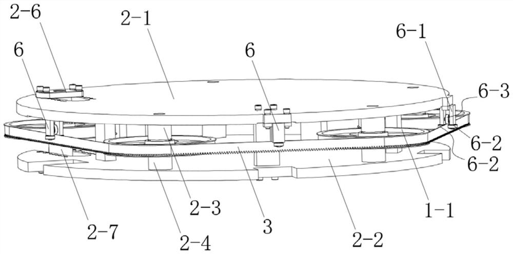
[0048] This embodiment also includes a guide assembly 6 . A plurality of guide assemblies 6 are provided on the drive wheel mount 2 . Each guide assembly 6 is respectively located above each pinion shaft assembly 4, and is used to limit the shaking of the flexible rack ring 3.

[0049] The guide assembly 6 includes a fixing part 6-1 and side guide wheels 6-2. The fixing part 6-1 is fixed on the drive wheel mounting seat 2. Two side guide wheels 6-2 are rotatably connected to the fixing member 6-1, and the peripheral surfaces of the two side guide wheels 6-2 are attached to the two sides of the flexible rack ring 3 respectively.

[0050] The guide assembly 6 also includes a top guide wheel 6-3. The top guide wheel 6-3 is rotatably connected to the fixing member 6-1, and the peripheral surface of the top guide wheel 6-3 is attached to the top surface of the flexi...


PUM


Abstract

The invention discloses a non-parallel shaft transmission-based multi-shaft synchronous transmission device. The non-parallel shaft transmission-based multi-shaft synchronous transmission device comprises a transmission wheel assembly, a transmission wheel mounting seat, a flexible gear rack ring, gear shaft assemblies, bases and guide assemblies; the transmission wheel assembly is arranged on thetransmission wheel mounting seat and comprises a plurality of the transmission wheels which support the flexible gear rack ring from the interior of the flexible gear rack ring and link with the flexible gear rack ring; teeth are formed at the bottom of the flexible gear rack ring; a plurality of the bases are uniformly distributed along the bottom edge of the transmission wheel mounting seat; aplurality of the gear shaft assemblies are respectively mounted on the plurality of the bases; the gear shaft assemblies are engaged with the flexible gear rack ring; a plurality of the guide assemblies are arranged on the transmission wheel mounting seat; and each guide assembly is positioned above the corresponding gear shaft assembly and is used for limiting the shaking of the flexible gear rack ring. The non-parallel shaft transmission-based multi-shaft synchronous transmission device is ingenious in structure; and synchronous mechanical transmission of a plurality of non-parallel transmission shafts is realized by matching the flexible gear rack ring and the gear shaft assemblies.

Description

technical field [0001] The invention relates to a multi-shaft synchronous transmission device for non-parallel shaft transmission. Background technique [0002] Transmissions are widespread in the field of machinery. At present, the existing drive shaft transmission devices usually adopt two transmission modes: parallel axis transmission and vertical axis transmission; the parallel axis transmission method has a large transmission space, and can only be one-to-one transmission, which occupies a large space and production costs; The vertical axis transmission is usually driven by the cooperation of gears and transmission shafts. The input part and the output part are in a vertical position relationship. The vertical axis transmission cannot be applied to multi-point transmission alone, and multiple vertical axis transmission devices are required for transmission separately. Just need a plurality of electric motors to drive, and production cost is high, and takes up a lot of ...

Claims


Application Information

Patent Timeline
Patent Type & Authority Patents(China)
IPC IPC(8): F16H7/02F16H7/18
CPCF16H7/023F16H7/18F16H2007/185
Inventor 刘光新朱江胡盘峰孙磊厚岳东海王萍柳岸敏赵茜
Owner CHANGZHOU COLLEGE OF INFORMATION TECH
Why Eureka
Try Eureka