A structure for self-controlled low pressure normally open decompression

A low-pressure, pressure-reducing valve technology, applied in separation methods, filtration separation, functional valve types, etc., can solve problems such as difficulty in ensuring water output, affecting life and production, etc.

Active Publication Date: 2020-01-21
NINGBO JIEKELONG PRECISION MFG
View PDF6 Cites 0 Cited by
  • Summary
  • Abstract
  • Description
  • Claims
  • Application Information

AI Technical Summary

Problems solved by technology

[0003] At present, because the outlet pressure of the existing pressure reducing valve installation pipeline is generally greater than 0.1MPa, but the selection principle of the water supply pressure reducing valve is that the minimum pressure before the valve is 0.2MPa greater than the dynamic pressure behind the valve, resulting in a relatively high pressure in the pipeline network. When the pressure is low, when the difference between the primary pressure and the secondary pressure is very small, it is difficult for the pressure reducing valve to ensure water discharge due to insufficient pressure in front of the valve, which seriously affects people's life and production, causing great inconvenience

Method used


Image

  • A structure for self-controlled low pressure normally open decompression
  • A structure for self-controlled low pressure normally open decompression
  • A structure for self-controlled low pressure normally open decompression

Examples


Embodiment Construction

[0031] In order to make it easy to understand the technical means, creative features, goals and effects achieved by the present invention, the following examples are combined with the appended figure 1 To attach Figure 4 The technical solutions provided by the present invention are described in detail, but the following content is not intended as a limitation of the present invention.

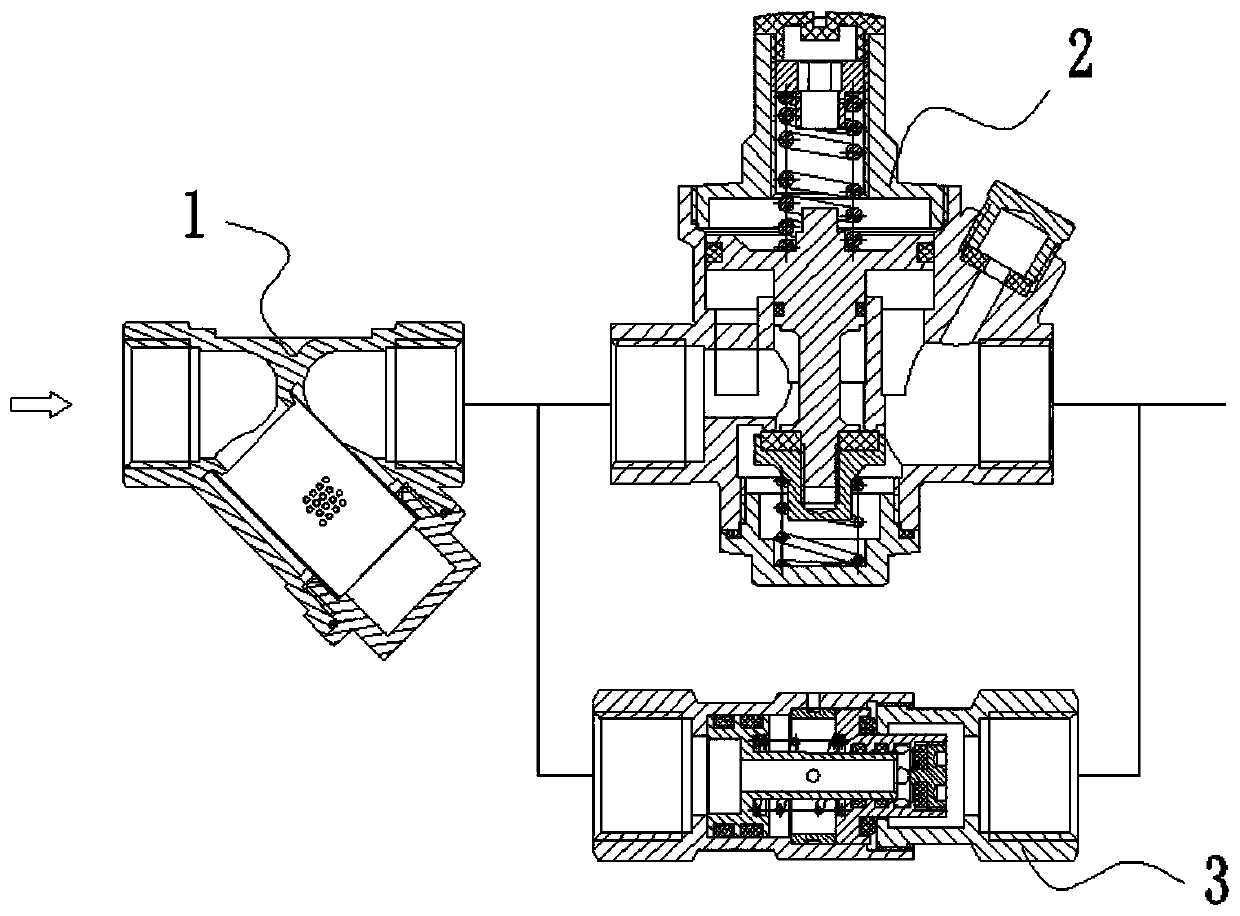
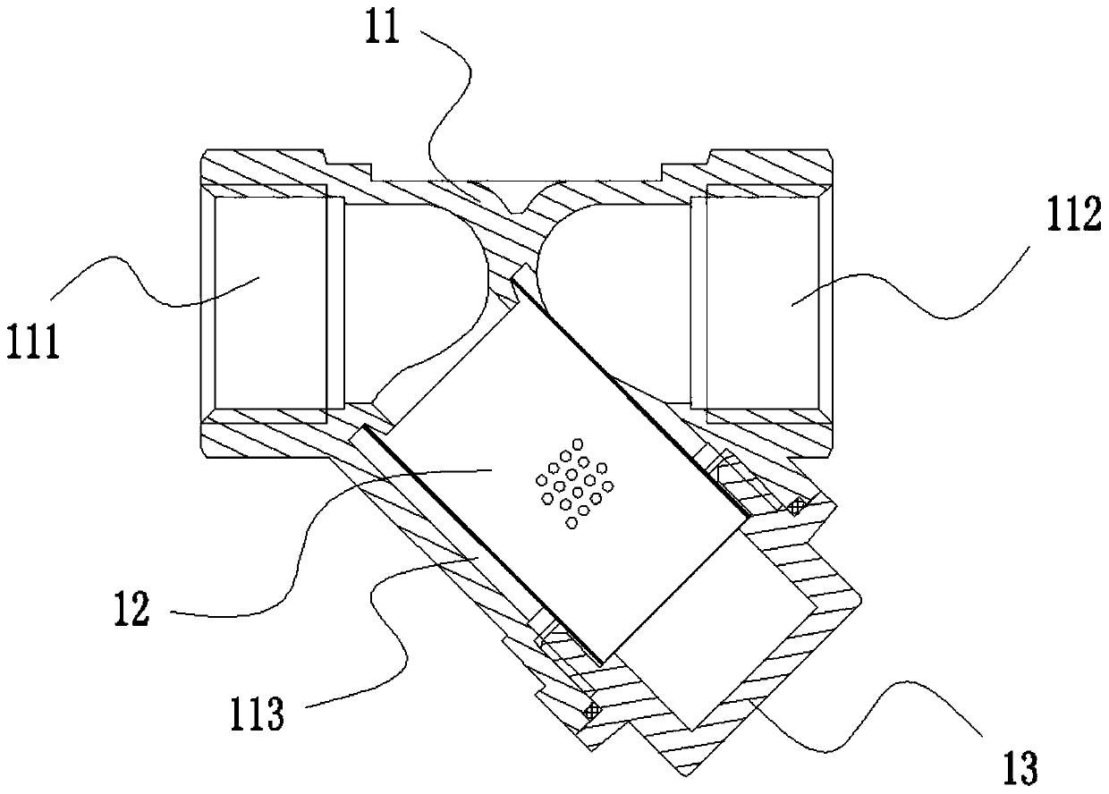
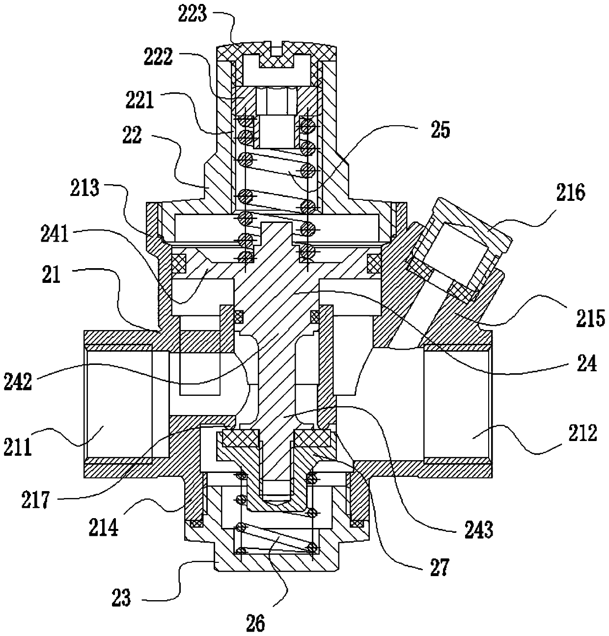
[0032] figure 1 It is a structural diagram of an embodiment of a self-controlled low-pressure normally-open decompression structure of the present invention. Such as figure 1 As shown, the structure of the self-controlled low pressure normally open decompression provided by this embodiment includes: a filter 1 and a pressure regulating structure, the filter 1 and the pressure regulating structure are connected in series, the filter 1 is arranged on the installation pipeline, and the filter 1 The outlet is connected to the inlet of the pressure regulating structure, and the outlet of the pre...


PUM


Abstract

The invention provides a self-operated control type low-pressure normally-open structure for pressure reduction, and belongs to the technical field of adjusting and controlling devices. The self-operated control type low-pressure normally-open structure for pressure reduction comprises a filter, a pressure reducing valve and a low-pressure normal open valve. According to the self-operated controltype low-pressure normally-open structure for pressure reduction, the filter is arranged, so that blockage of the pressure reducing valve and the low-pressure normal open valve is prevented, meanwhile, impurities can be filtered, and the fluid with higher cleanliness is provided; the pressure reducing valve and the low-pressure normally-open valve can be arranged in parallel, so that when upstreampressure is large, the pressure reducing valve can be opened, the low-pressure normal open valve can be closed, and the pressure reduction and supply of the fluid are realized; when the pressure reducing valve cannot be opened under the condition that the upstream pressure is small, the low-pressure normal open valve is opened, the supply of the fluid can also be realized; and the adaptability ishigher, so that normal proceeding of people in production and life is guaranteed, the influence on the production and life of people is avoided, and supportability of the self-operated structure is higher.

Description

technical field [0001] The invention relates to the technical field of regulating control devices, in particular to a structure for self-controlling low pressure normally open and decompressing. Background technique [0002] In people's production and life, such as domestic water supply system, fire protection system, production water supply and other composite water supply systems, pressure reducing valves are often used as fluid pressure reducing devices. By changing the throttling area, a certain pressure loss is caused, so that The flow rate and kinetic energy of the fluid are reduced to achieve the purpose of decompression, and with the adjustment of the control and regulation system, the fluctuation of the pressure behind the valve is balanced with the spring force in the valve body, so that the pressure behind the valve remains constant within a certain error range . [0003] At present, because the outlet pressure of the existing pressure reducing valve installation...

Claims


Application Information

Patent Timeline
Patent Type & Authority Patents(China)
IPC IPC(8): F16K17/32F16K17/04B01D35/02
CPCB01D35/02F16K17/04F16K17/32
Inventor 祝文耀蔡小飞黄水清严荣杰
Owner NINGBO JIEKELONG PRECISION MFG
Why Eureka
Try Eureka