
Step gauge

A technology of ladder gauges and spacers, which is applied in the field of ladder gauges, can solve problems such as stress changes and size changes of ladder gauges, achieve high-precision calibration processing, and suppress dimensional changes.

Inactive Publication Date: 2018-12-07
MITUTOYO CORP
View PDF7 Cites 0 Cited by
  • Summary
  • Abstract
  • Description
  • Claims
  • Application Information

AI Technical Summary

Problems solved by technology

[0006] However, even if the blocks are formed using extremely low expansion materials as described above, when the linear expansion coefficient of the connecting tool used to connect these blocks is large, the stress used to connect the blocks may occur due to temperature changes. change, the overall size of the ladder gauge changes

Method used


Image

  • Step gauge
  • Step gauge
  • Step gauge

Examples


Embodiment Construction

[0021] Hereinafter, a step gauge according to one embodiment of the present invention will be described.

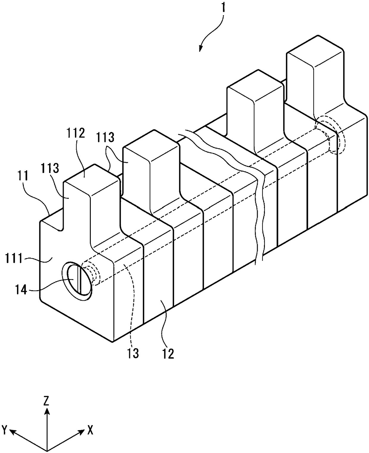
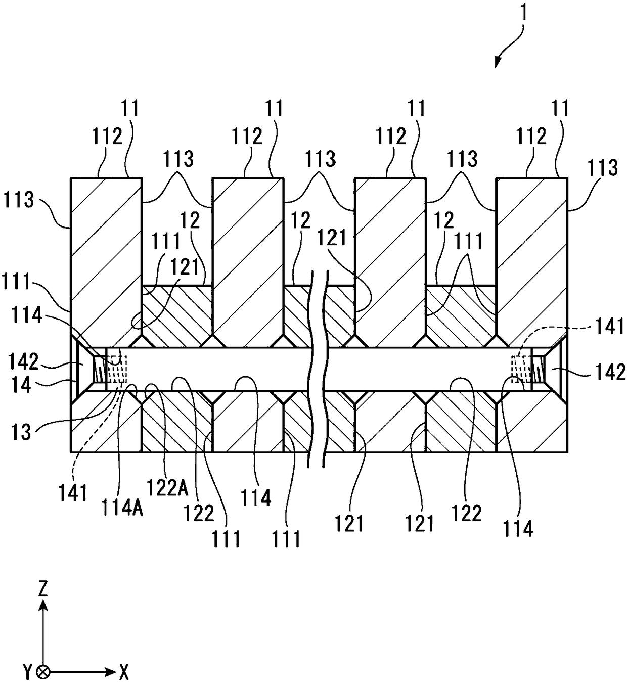
[0022] figure 1 It is a schematic perspective view of the step gauge of this embodiment. figure 2 It is a sectional view along the longitudinal direction of the step gauge of this embodiment.

[0023] The stepped gauge 1 is a standard gauge that becomes long along one direction (X direction). like figure 1 as well as figure 2 As shown, the ladder gauge 1 includes a plurality of gauge blocks 11, a plurality of spacer blocks 12, a pull rod 13 (shaft material) for connecting these gauge blocks 11 and spacer blocks 12, and two ends of the pull rod 13. Countersunk screw 14 (fixed part).

[0024] The gauge block 11 includes a first side 111 extending along a plane intersecting the X direction (orthogonal in this embodiment), and protruding along a Z direction intersecting with the X direction (orthogonal in this embodiment). The measuring part 112.

[0025] The first...


PUM


Abstract

A step gauge 1 includes measurement blocks 11 each having reference measurement surfaces 113; interval blocks 12 each interposed between a pair of ones 11 of the measurement blocks 11 to keep a distance between the pair of ones of the measurement blocks at a predetermined distance, the measurement blocks 11 and the interval blocks 12 being alternately aligned one by one in one direction. The measurement blocks 11 and the interval blocks 12 each have a coefficient of linear thermal expansion of less than 0.03*1-6(1 / K) and have through holes 114, 122 aligned in the one direction. The step gauge1 further includes a tie rod 13 inserted in the through holes 114, 122 and countersunk screws 14 respectively fixed to ends of the tie rod 13. The tie rod 13 is made of a material having a coefficientof linear thermal expansion of less than 0.5*10-6(1 / K).

Description

technical field [0001] The invention relates to a stepped gauge formed by connecting a plurality of end surface measuring tools together. Background technique [0002] Conventionally, among measuring devices for measuring the surface shape, size, etc. of an object to be measured, there is known a measuring device that performs a calibration process using a step gauge provided with a reference measuring surface at predetermined intervals (Document 1: Japanese Patent Laid-Open 2004-125665 Bulletin). In such a measuring device, it is possible to perform dimensional calibration by measuring the reference measuring surfaces of the step gauge arranged at regular intervals. [0003] Generally, such a step gauge is formed by combining a gauge block (end gauge) having a reference measurement surface and a spacer block arranged between a pair of gauge blocks to strictly maintain the distance between the reference measurement surfaces at a set size. Arranged alternately so as to be j...

Claims


Application Information

Patent Timeline
Patent Type & Authority Applications(China)
IPC IPC(8): G01B5/00
CPCG01B5/0014G01B3/30G01B21/042G01B5/0002G01B5/204
Inventor 鸣海达也松浦章彦矢野健太郎
Owner MITUTOYO CORP
Learn More