Phase difference film used for VA, manufacturing method of phase difference film used for VA, polarizing film, and vertical orientation type liquid crystal display device

A technology of retardation film and manufacturing method, applied in polarizing elements, instruments, optical elements, etc., can solve problems such as color tone change, and achieve the effect of improving the durability of damp heat

Active Publication Date: 2017-01-25
KONICA MINOLTA INC
View PDF16 Cites 2 Cited by
  • Summary
  • Abstract
  • Description
  • Claims
  • Application Information

AI Technical Summary

Problems solved by technology

In the case of using a cellulose ester retardation film, fluctuations in retardation under high-humidity environments and consequent changes in the color tone of images displayed on liquid crystal display devices become a problem

Method used

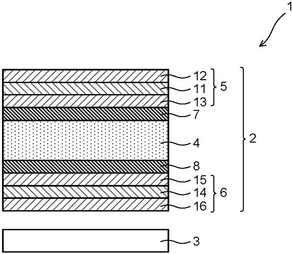
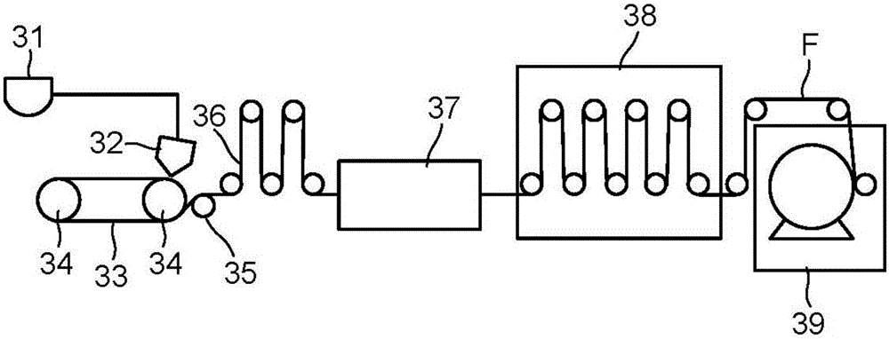

Image

  • Phase difference film used for VA, manufacturing method of phase difference film used for VA, polarizing film, and vertical orientation type liquid crystal display device
  • Phase difference film used for VA, manufacturing method of phase difference film used for VA, polarizing film, and vertical orientation type liquid crystal display device
  • Phase difference film used for VA, manufacturing method of phase difference film used for VA, polarizing film, and vertical orientation type liquid crystal display device

Examples


Synthetic example

[0239]

[0240] Below, the synthesis example of a sugar ester is shown.

[0241] [Chemical formula 15]

[0242]

[0243] 34.2 g (0.1 mol) of sucrose, 180.8 g (0.8 mol) of benzoic anhydride, and 379.7 g (4.8 mol) of pyridine were placed in a four-necked flask equipped with a stirring device, a reflux cooler, a thermometer, and a nitrogen introduction tube, respectively. While bubbling nitrogen gas from a nitrogen gas introduction pipe with stirring, the temperature was increased, and the esterification reaction was performed at 70° C. for 5 hours. Next, the inside of the flask was depressurized to 4×10 2 Pa or less, after distilling off excess pyridine at 60°C, the inside of the flask was depressurized to 1.3×10Pa or less, and the temperature was raised to 120°C to distill off benzoic anhydride and most of the generated benzoic acid. Then, 1 L of toluene and 300 g of a 0.5 mass % sodium carbonate aqueous solution were added, and the mixture was stirred at 50° C. for 30 m...

Embodiment

[0413] Hereinafter, although an Example is given and this invention is demonstrated concretely, this invention is not limited to these Examples. In addition, in an Example, the representation of "part" or "%" is used, unless otherwise specified, "mass part" or "mass %" is represented.

[0414]

[0415]

[0416] Microparticles (AEROSIL R812 manufactured by Japan AEROSIL Co., Ltd.) 11 parts by mass

[0417] Ethanol 89 parts by mass

[0418] The above substances were stirred and mixed with a dissolving bar for 50 minutes, and then dispersed with Manton-Gaulin to prepare a particle dispersion liquid 1.

[0419]

[0420] The fine particle dispersion liquid 1 was gradually added to the dissolving tank in which dichloromethane was placed while stirring well. Further, dispersion is carried out with an Attritor so that the particle diameter of the secondary particles becomes a predetermined size. This was filtered with FINE MET NF manufactured by Nippon Seisen Co., Ltd. to prep...


PUM

PropertyMeasurementUnit
Particle sizeaaaaaaaaaa

Abstract

The invention discloses a phase difference film used for VA comprising cellulose ester resin and satisfying following conditions (1) and (2). According to the condition (1): smd plus std is smaller than or equal to 0.65%, and smd and std respectively represent the size change rates (5) of the film taking the 55% RH state as the reference during the changing from 20% RH to 80% at 23DEG C in the length direction and the width direction. According to the condition (2):rth 2-rth1 is smaller than or equal to 9nm, and rth 1 represents the measured delay (nm) of the thickness direction, when two transparent substrates are used to clamp the film without using adhesive agent, and rth 2 represents the measured delay (nm) of the thickness direction, when the two transparent substrates are used to clamp the film, and the adhesive agent exists between the film and one of the transparent substrates.

Description

technical field [0001] The present invention relates to a retardation film for VA applicable to a vertical alignment type (VA type; Vertical Alignment) liquid crystal display device, a method for producing the retardation film for VA, a polarizing plate using the retardation film for VA, and a vertical alignment type liquid crystal display device using the polarizer. Background technique [0002] As an optical compensation film used for a VA type liquid crystal display device, a retardation film for VA containing a cellulose ester resin is known (hereinafter, the above film is also described as a cellulose ester retardation film, or only a film). ). When a cellulose ester-based retardation film is used, a change in the retardation in a high-humidity environment and a change in the color tone of an image displayed in a liquid crystal display device are a problem. The following factors are presumed to be one of the factors causing the color tone change. [0003] When a cell...

Claims


Application Information

Patent Timeline
IPC IPC(8): G02B5/30G02F1/1335
CPCG02B5/3083G02F1/133528C08J5/18C08L1/12G02B5/3033
Inventor 金子由纪
Owner KONICA MINOLTA INC
Why Eureka
Try Eureka