Condensing lens interface line drawing method and device, medium and electronic device

A condensing lens and interface technology, which is applied in the field of solar energy, can solve the problems of inability to guarantee the design accuracy of the condensing lens interface angle, low efficiency, and cumbersome design process of the condensing lens interface.

Pending Publication Date: 2018-12-07
BEIJING HANERGY PV TECH CO LTD
View PDF4 Cites 0 Cited by
  • Summary
  • Abstract
  • Description
  • Claims
  • Application Information

AI Technical Summary

Problems solved by technology

It can be seen that the design process of the condenser lens interface in the prior art is very cumbers

Method used


Image

  • Condensing lens interface line drawing method and device, medium and electronic device
  • Condensing lens interface line drawing method and device, medium and electronic device
  • Condensing lens interface line drawing method and device, medium and electronic device

Examples


Embodiment Construction

[0066] Specific embodiments of the present disclosure will be described in detail below in conjunction with the accompanying drawings. It should be understood that the specific embodiments described here are only used to illustrate and explain the present disclosure, and are not intended to limit the present disclosure.

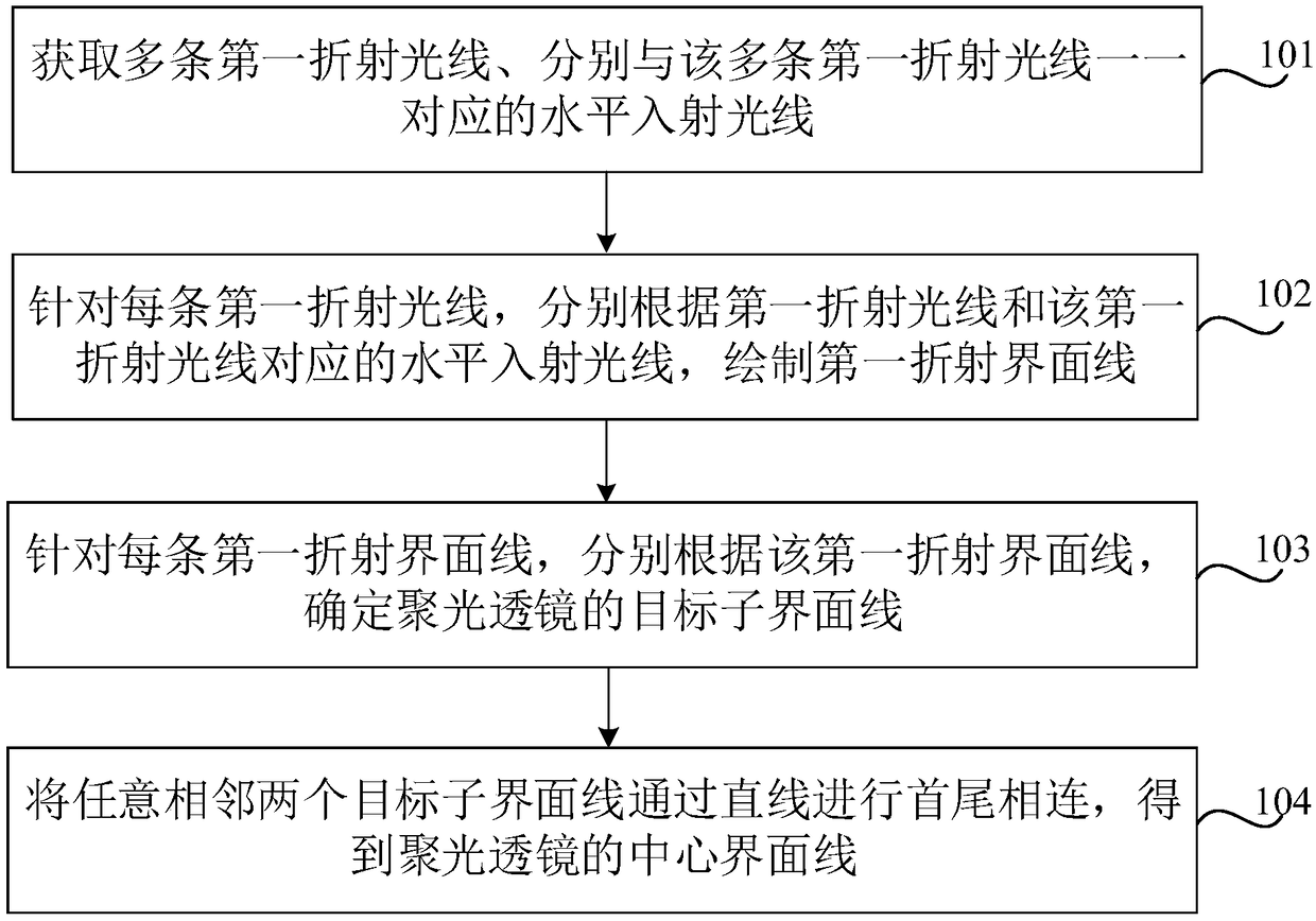
[0067] figure 1 It is a flow chart of a method for drawing an interface line of a condenser lens according to an exemplary embodiment. Such as figure 1 As shown, the method may include the following steps.

[0068] In step 101, a plurality of first refracted rays and horizontal incident rays respectively corresponding to the plurality of first refracted rays one-to-one are obtained.

[0069] In the present disclosure, the above-mentioned multiple first refracted rays converge on a focusing surface to form a spot; and, the number of the first refracted rays is equal to the number of tooth lines of the condenser lens plus 1, for example, the teeth of the con...


PUM


Abstract

The present invention relates to a condensing lens interface line drawing method and device, a medium and an electronic device. The method comprises the steps of: obtaining a plurality of first refracted rays and horizontal incident rays being in one-to-one correspondence with the first refracted rays, wherein the first refracted rays are collected on a focusing surface to form a light spot; for the first refracted rays, drawing a first refraction interface line according to the first refracted rays and the horizontal incident rays corresponding to the first refracted rays; determining targetsub interface lines of a condensing lens according to the refraction interface line for each first refracted rays; and performing end-to-end connection for each two target sub interface lines throughstraight lines to obtain a center interface line of the condensing lens. Therefore, the drawing of the certain interface line of the condensing lens in the concentrating photovoltaic lens design can be achieved, the drawing is high, and the design precision of the angle of the central interface line of the condensing lens can be ensured.

Description

technical field [0001] The present disclosure relates to the technical field of solar energy, and in particular, relates to a drawing method, device, medium and electronic equipment of a concentrating lens interface line. Background technique [0002] The design of CPV mainly involves the design of the interface of the condensing lens, so that the light can be focused on a plane after passing through the interface of the condensing lens. When the existing drawing software designs the interface of the condenser lens, it is necessary to set a close interface based on experience, and then check whether it conforms to the law of refraction according to the incident light and the corresponding refraction path; if it does not conform to the law of refraction , then adjust the interface angle, check again, and repeat this until the error meets the preset requirements. It can be seen that the design process of the interface of the condensing lens in the prior art is very cumbersome...

Claims


Application Information

Patent Timeline
IPC IPC(8): G02B27/00G02B19/00
CPCG02B19/0009G02B19/0042G02B27/0012
Inventor 王超平
Owner BEIJING HANERGY PV TECH CO LTD
Why Eureka
Try Eureka