Display screen for GPS
A display screen and blade technology, applied in the field of display screens, can solve problems such as easy to scratch the display screen, poor effect, and greater impact on the user's viewing of display screen information, to achieve protection of the display screen, high screen-to-body ratio, and shrink area effect
- Summary
- Abstract
- Description
- Claims
- Application Information
AI Technical Summary
Problems solved by technology
Method used
Image
Examples
Embodiment 1
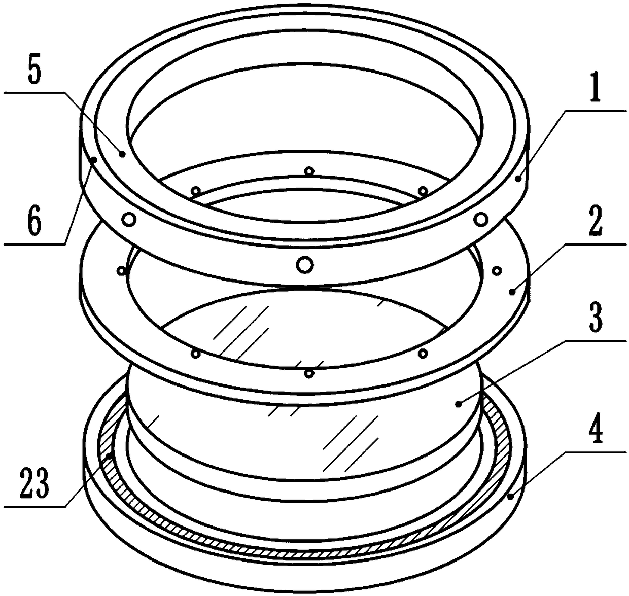
[0045] Such as figure 1 As shown, the display screen 3 for GPS includes a base 4 , a top frame 1 , a middle frame 2 and a circular display screen 3 installed on the base 4 .
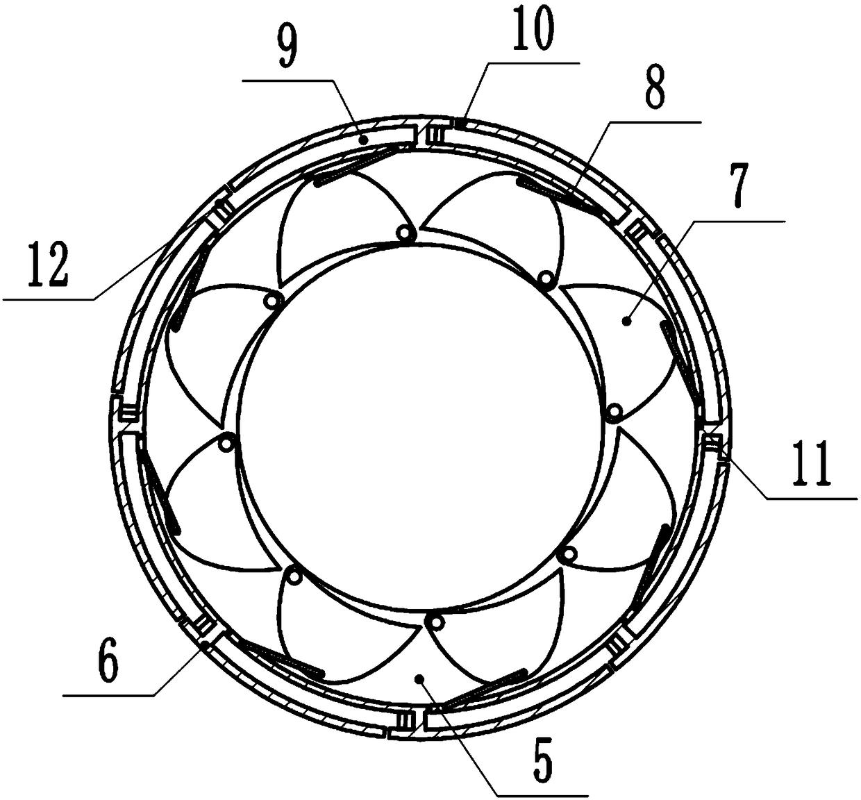
[0046] The top frame 1 includes an inner ring 5, an outer ring 6, 7 sets of blades and 8 sets of connecting rods;
[0047] Such as image 3 As shown, the outer ring 6 covers the outer circumference of the inner ring 5, the outer ring 6 and the inner ring 5 have a common center, and the outer ring 6 and the inner ring 5 are rotatably connected; the outer ring 6 rotates around the center of the circle; The arc-shaped cavities 9, in this embodiment, the number of cavities 9 is 8. One end of the cavity 9 is provided with an air inlet 10, and the other end is provided with an exhaust hole, and the exhaust hole faces the direction of the center of the outer ring 6; a baffle 12 is provided inside the cavity 9, and the initial position of the baffle 12 is located at the air intake of the cavity 9. At the end ...
Embodiment 2
[0059] The display screen 3 used for GPS differs from Embodiment 1 in that:
[0060] Also includes control components, detection components and main board;
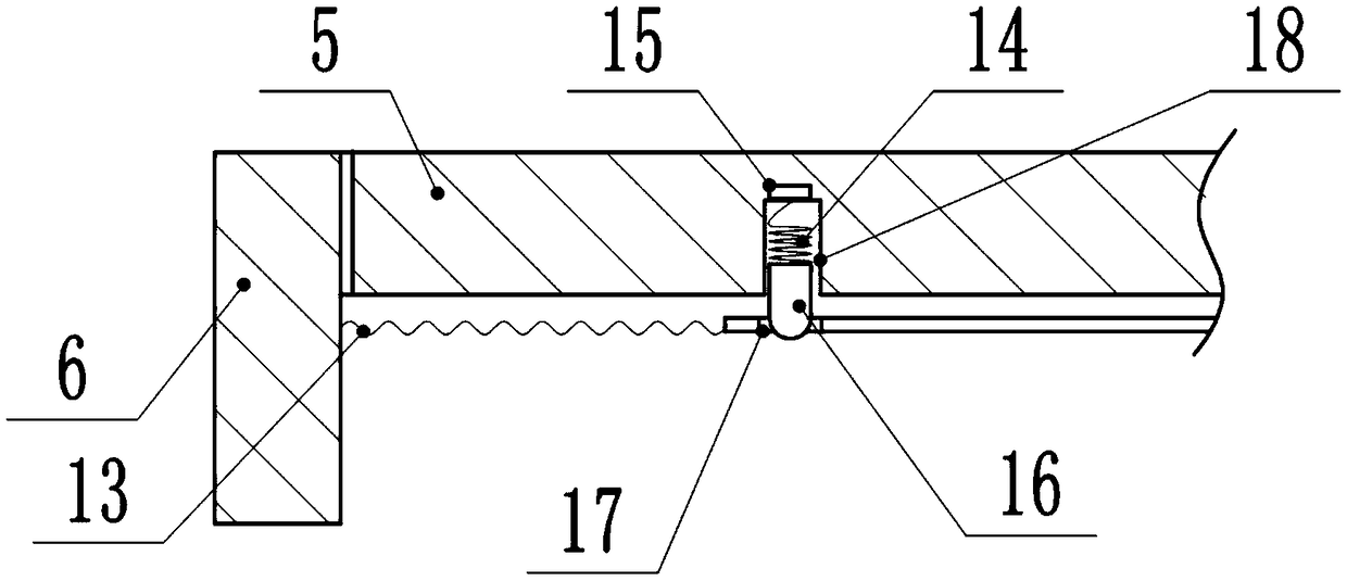
[0061] Such as figure 2 As shown, the control assembly includes a first spring 13, a second spring 14, an electromagnet 15 and an iron block 16;
[0062] The left end of the first spring 13 is welded to the outer ring 6, and the right end is bonded to the middle part of the blade 7 away from the side of the display screen 3; when the blade 7 is not rotating, the first spring 13 is in a compressed state;
[0063] A limit hole 17 is provided on the blade 7, and the lower surface of the inner ring 5 facing the limit hole 17 is provided with a first groove 18. The iron block 16 is in clearance fit with the first groove 18, and the electromagnet 15 is bonded to the first groove 18. A groove 18 is away from display screen 3 one end; The second spring 14 upper end is bonded with electromagnet 15, and the lower end is bonded w...
PUM
 Abstract
Description
Claims
Application Information
 - R&D
- Intellectual Property
- Life Sciences
- Materials
- Tech Scout
- Unparalleled Data Quality
- Higher Quality Content
- 60% Fewer Hallucinations
Browse by: Latest US Patents, China's latest patents, Technical Efficacy Thesaurus, Application Domain, Technology Topic, Popular Technical Reports.
© 2025 PatSnap. All rights reserved.Legal|Privacy policy|Modern Slavery Act Transparency Statement|Sitemap|About US| Contact US: help@patsnap.com


