

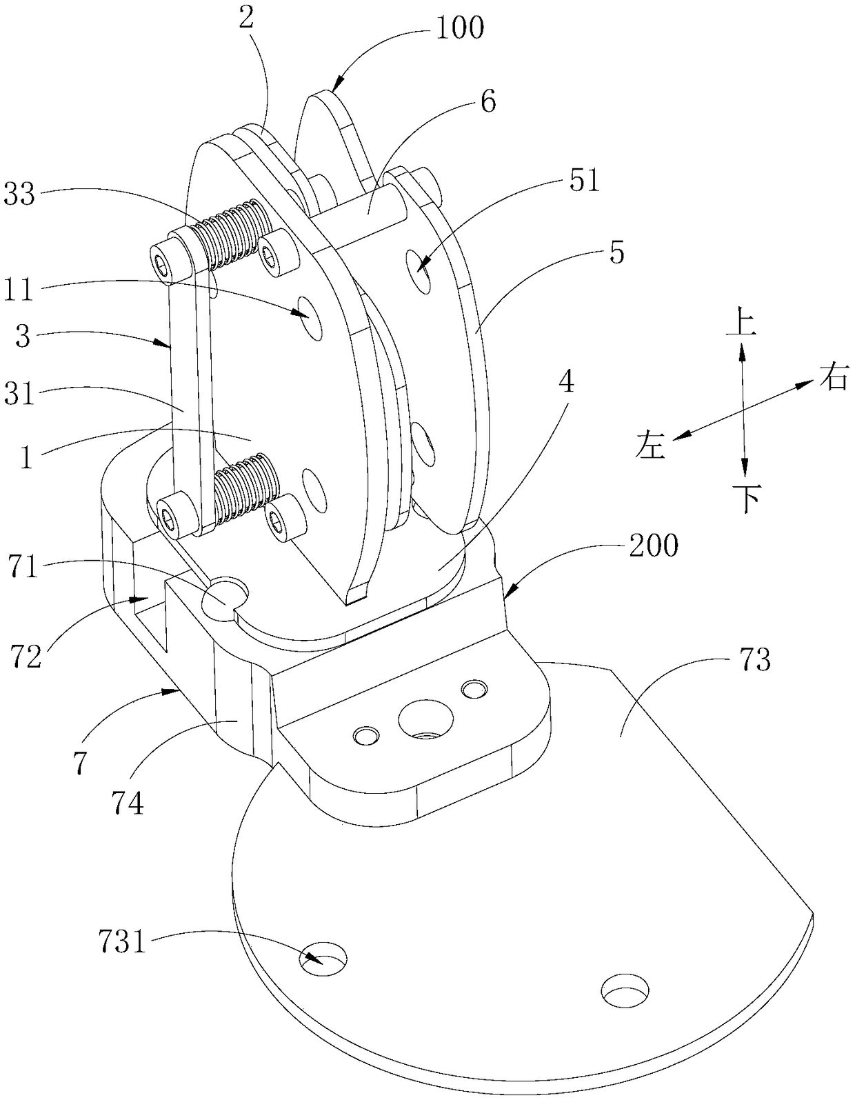
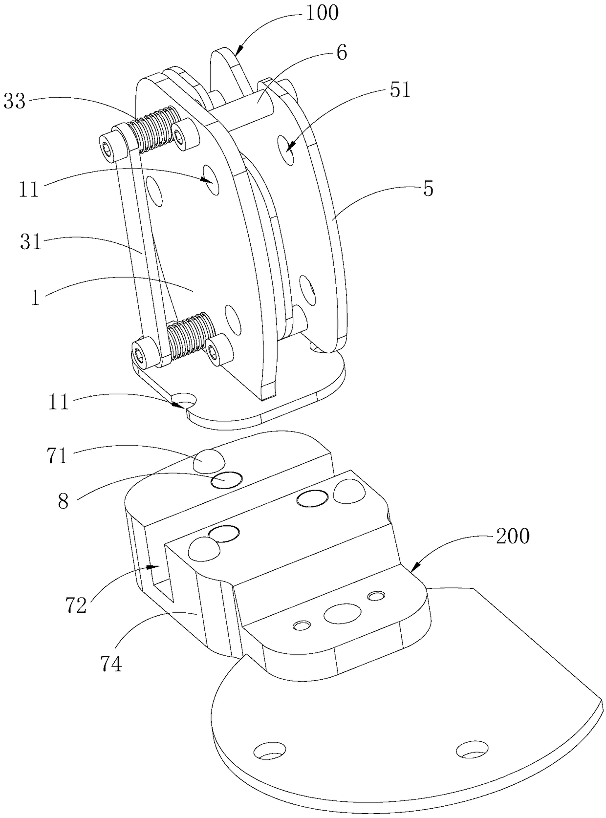
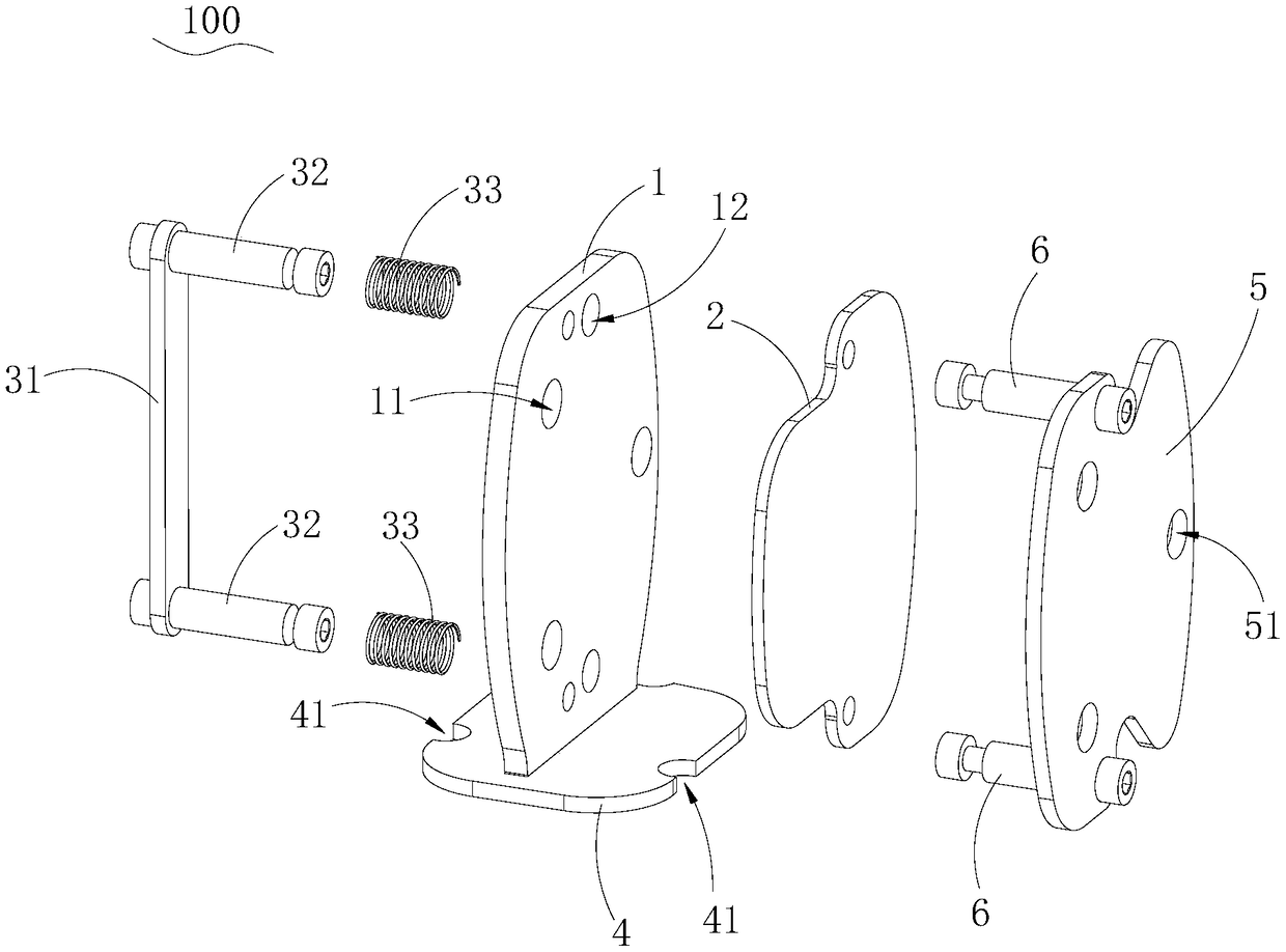
False tooth impression clamp
An impression and fixture technology, applied in the field of denture impressions, can solve the problems of scan failure, denture impression shaking, and inability to meet the one-time scanning of double-sided impressions.
- Summary
- Abstract
- Description
- Claims
- Application Information
AI Technical Summary
Problems solved by technology
Method used
Image

Examples
Embodiment Construction
[0027] The technical solutions in this embodiment will be clearly and completely described below in conjunction with the accompanying drawings in this embodiment. Obviously, the described embodiments are only part of the embodiments of the present invention, not all of them. Based on the embodiments of the present invention, all other embodiments obtained by persons of ordinary skill in the art without making creative efforts fall within the protection scope of the present invention.
[0028] It should be noted that all directional indications (such as up, down, left, right, front, back...) in this embodiment are only used to explain the relative relationship between the various components in a certain posture (as shown in the figure). When the positional relationship, movement conditions, etc., if the specific posture changes, the directional indication will also change accordingly.
[0029] In addition, in the present invention, descriptions such as "first", "second" and so ...
PUM
 Abstract
Description
Claims
Application Information