Video camera module

A camera and lens technology, which is applied in the field of camera modules for auto-focusing, can solve the problems of large offset of the shielding shell, positioning of the shielding shell, shaking of the shielding shell, etc.

Inactive Publication Date: 2012-05-30
MITSUMI ELECTRIC CO LTD
View PDF9 Cites 13 Cited by
  • Summary
  • Abstract
  • Description
  • Claims
  • Application Information

AI Technical Summary

Problems solved by technology

However, only by extending the lower end of the shield case, there is still a gap (gap) between the shield case, the driver body and the base member
As a result, the shield case shakes
In addition, there is a problem that the shield case is installed obliquely with respect to the sensor substrate due to the rotational shak

Method used


Image

  • Video camera module
  • Video camera module
  • Video camera module

Examples


Embodiment Construction

[0029] Hereinafter, embodiments of the present invention will be described with reference to the drawings.

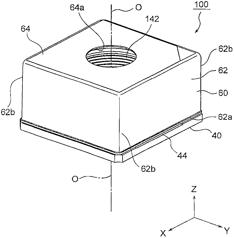
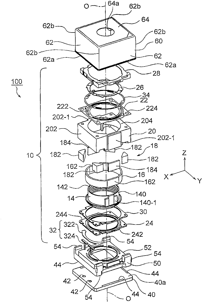
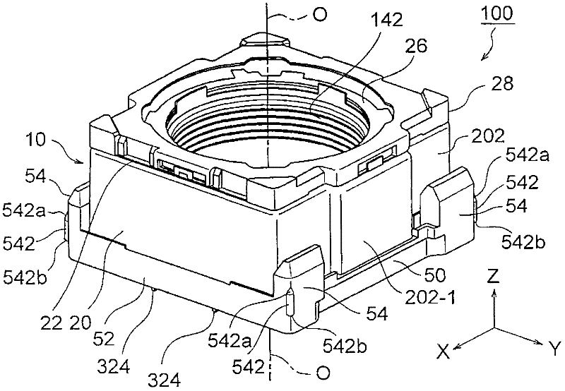
[0030] refer to Figure 1 to Figure 5 , the camera module 100 according to the first embodiment of the present invention will be described. figure 1 is a perspective view showing the appearance of the camera module 100, figure 2 is an exploded perspective view of the camera module 100 . image 3 is expressed in figure 2 In the shown camera module 100 , it is a perspective view of a state in which the driver main body 10 and the base member 50 are assembled. Figure 4 is expressed in figure 2 In the shown camera module 100 , it is a perspective view of an assembled state of the driver main body 10 , the base member 50 , and the sensor substrate 40 . Figure 5 is in figure 2 The illustrated camera module 100 is a cross-sectional view in which the sensor substrate 40 is omitted.

[0031] here, as Figure 1 to Figure 5 As shown, an orthogonal coordinate system ...


PUM


Abstract

Provided is a video camera module capable of easily and precisely positioning a shielding housing upon a sensor substrate in a shake-proof manner. The video camera module (100) comprises: a driver body (10) that supports a lens assembly in a manner capable of moving in the direction along the optical axis (O) of a lens, a sensor substrate (40) carrying a shooting element, a substrate member (50) arranged between the driver body and the sensor substrate, and a shielding housing (60) covering the upper surface (40a) of the driver body, the substrate member, and the sensor substrate for shielding the electromagnetic noises generated from the sensor substrate. In the structure, the upper end (60a) of the shielding housing (60) extends to the upper surface (40a) of the sensor substrate (40). The substrate member (50) comprises at least two protruding parts (542) protruding toward the outboard in the radius direction. The shielding housing (60) is jogged with the two protruding parts in a light-pressing manner.

Description

technical field [0001] The present invention relates to a camera module, in particular to a camera module for auto-focusing used in a portable compact camera. Background technique [0002] A portable compact video camera is mounted on a mobile phone with a video camera. A camera module of an autofocus lens drive device is used in this portable compact camera. Conventionally, various camera modules for autofocusing have been proposed. [0003] For example, Patent Document 1 (Japanese Patent Application Laid-Open No. 2009-271405 ) discloses a lens module that can be assembled with high positional accuracy. The lens module disclosed in this patent document 1 includes an actuator main body that supports the lens assembly so as to be movable along the optical axis direction of the lens, a sensor substrate on which an imaging element is mounted, and a base member disposed between the actuator main body and the sensor substrate. . In addition, Patent Document 1 discloses a lens...

Claims


Application Information

Patent Timeline
IPC IPC(8): H04N5/225
Inventor 大坂智彦石泽贵
Owner MITSUMI ELECTRIC CO LTD
Why Eureka
Try Eureka