Pipeline flow deflector type oil-water separator and water removing device thereof

A technology of oil-water separator and deflector, applied in the direction of liquid separation, separation methods, chemical instruments and methods, etc., can solve the problems of complex equipment and troublesome maintenance, achieve good adaptability, good oil-water separation effect, and improve oil-water separation efficiency effect

Inactive Publication Date: 2012-08-08
INST OF MECHANICS - CHINESE ACAD OF SCI
View PDF8 Cites 14 Cited by
  • Summary
  • Abstract
  • Description
  • Claims
  • Application Information

AI Technical Summary

Problems solved by technology

However, in the underground, the dynamic deflector is used to spin, which makes the equipment complicated and maintenance troublesome

Method used


Image

  • Pipeline flow deflector type oil-water separator and water removing device thereof
  • Pipeline flow deflector type oil-water separator and water removing device thereof
  • Pipeline flow deflector type oil-water separator and water removing device thereof

Examples


Embodiment Construction

[0035] Embodiments of the present invention will be described in detail below in conjunction with the accompanying drawings. It should be noted that, in the case of no conflict, the embodiments in the present application and the features in the embodiments can be combined arbitrarily with each other.

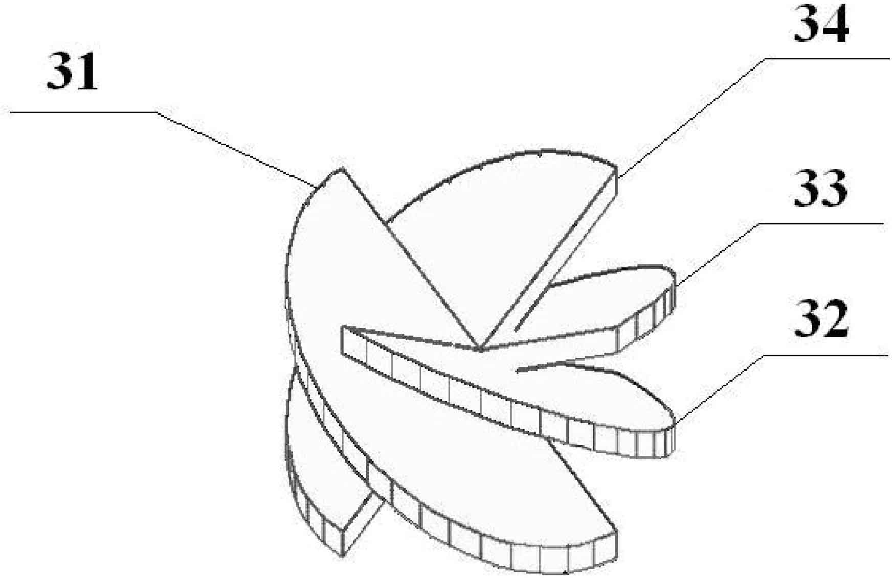
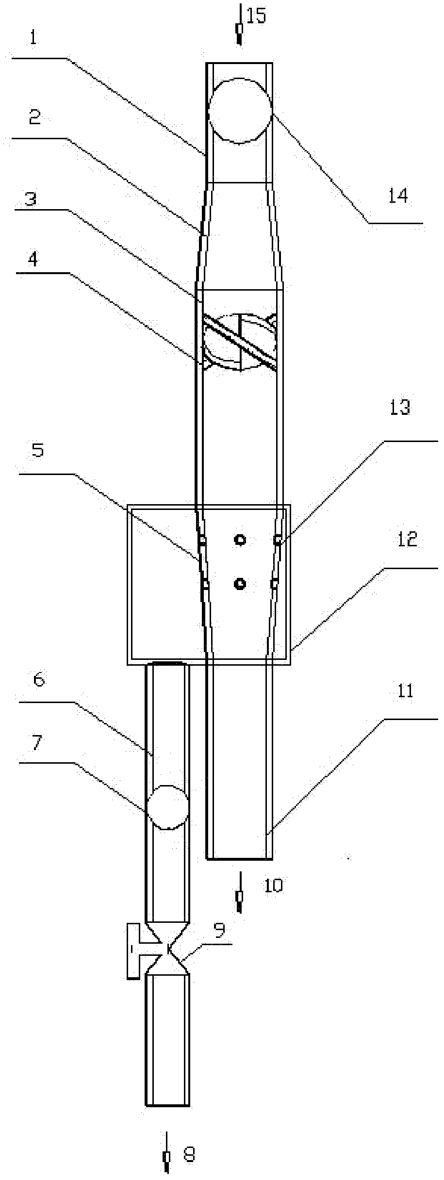
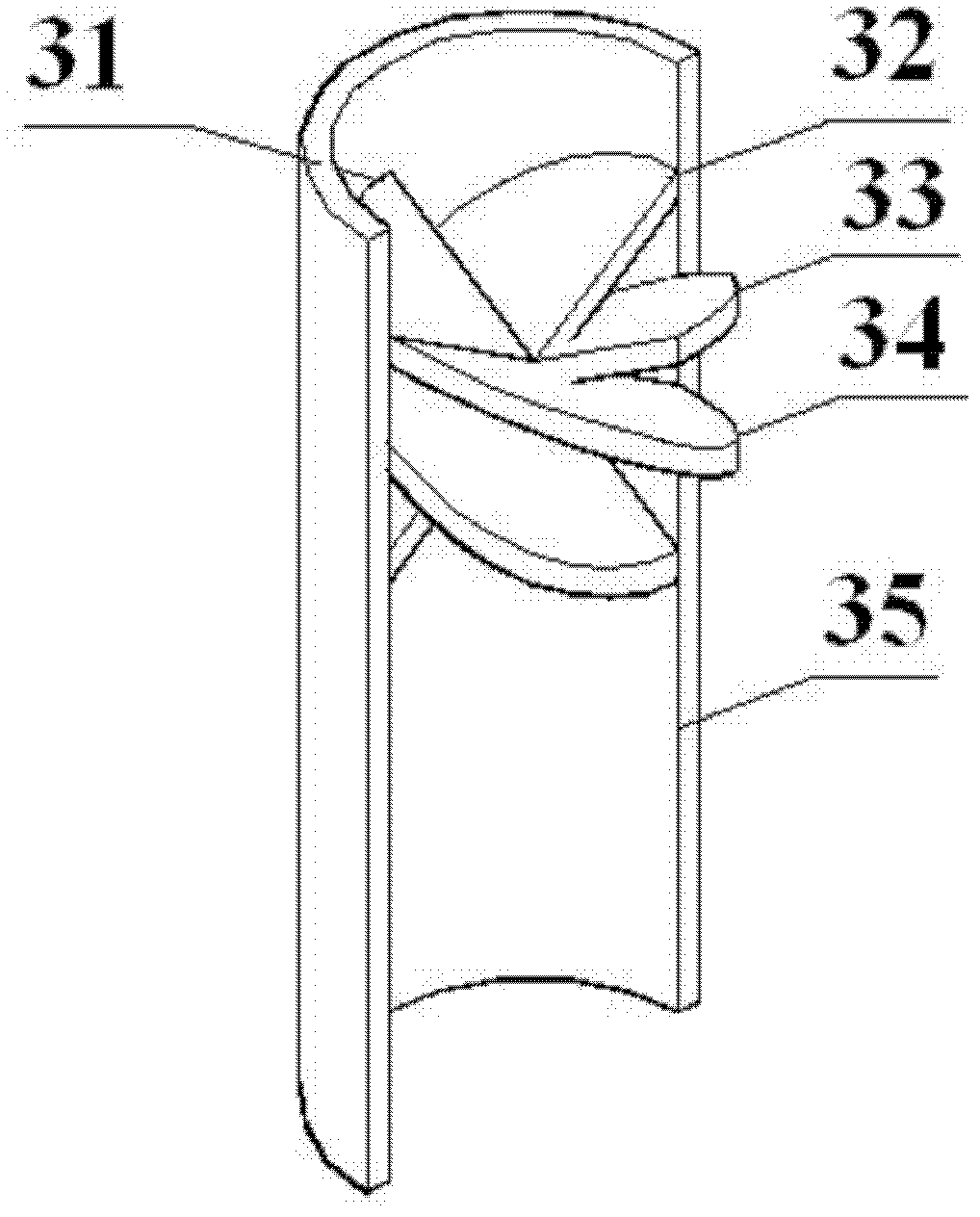
[0036] Such as figure 1 As shown, the present invention includes: the liquid inlet pipe section 1, the gradually expanding pipe section 2, the swirl flow generation pipe section 3 and the water removal pipe section 5 that are sequentially connected and arranged, because the inner diameter of the swirl flow pipeline of the swirl flow generation pipe section 3 is larger than the liquid inlet pipe section The inner diameter of the pipeline of the pipe section 1, therefore, the expanding pipe section 2 is set between the liquid inlet pipe section 1 and the swirl flow generation pipe section 3, and the first flowmeter 14 is installed on the liquid inlet pipe of the liquid inlet pipe ...


PUM


Abstract

The invention discloses pipeline flow deflector type oil-water separator and a water removing device thereof. The pipeline flow deflector type oil-water separator comprises a liquid inlet pipe segment, a gradually-expanding pipe segment, a rotational flow generating pipe segment and a water removing pipe segment which are connected in sequence, wherein the rotational flow generating pipe segment comprises a rotational flow pipeline and more than two flow deflectors which are fixedly and obliquely arranged in the rotational flow pipeline; when an oil-water mixed liquid flows through the flow deflectors, a centrally-symmetrical rotational-flow field is formed, so that oil and water are separated centrifugally; the water removing pipe segment comprises a water removing pipeline; the water removing pipeline is provided with an oil inlet and an oil outlet; and the oil removing pipeline is provided with over one group of water removing holes along the axial direction of the pipe. Due to the adoption of the oil-water separator, the symmetric stability of the rotational flow field can be improved, an oil-water separating technology is improved, the utilization ratio of an underground oil-water separator space is increased, and a good industrial application prospect is achieved.

Description

technical field [0001] The invention relates to an oil-water separator, in particular to a pipeline-type deflector-type oil-water separator and a water removal device used in an oil-water separation system downhole. Background technique [0002] With the prolongation of oilfield development time, water production continues to increase, which increases production costs. In order to reduce production costs, it has become a consensus to use downhole oil-water separators to separate water and reinject it into formations in situ. [0003] The separation principles currently used for downhole oil-water separation are mainly gravity and centrifugation. For example, the patent publication number: CN 101025080A, the method of multi-cup isoflow downhole oil-water separator to realize injection and production of high water-cut wells in the same well uses the principle of gravity. Oil and water are separated by natural sedimentation. Publication number: CN2931780, a downhole oil-water ...

Claims


Application Information

Patent Timeline
Patent Type & Authority Applications(China)
IPC IPC(8): B01D17/038
Inventor 吴应湘许晶禹史仕荧
Owner INST OF MECHANICS - CHINESE ACAD OF SCI
Why Eureka
Try Eureka