Mechanical clamp

A fixture and mechanical technology, applied in the field of mechanical fixtures, can solve the problems of poor versatility and difficulty in fixing, and achieve the effect of stable fixing method and convenient use

Inactive Publication Date: 2018-12-11
吴敏
View PDF0 Cites 2 Cited by
  • Summary
  • Abstract
  • Description
  • Claims
  • Application Information

AI Technical Summary

Problems solved by technology

[0004] The purpose of the present invention is to provide a kind of mechanical fixture, to solve the problems of poor versatility and difficult fixation in the above-mentioned background technology

Method used


Image

  • Mechanical clamp
  • Mechanical clamp
  • Mechanical clamp

Examples


Embodiment Construction

[0016] The following will clearly and completely describe the technical solutions in the embodiments of the present invention with reference to the accompanying drawings in the embodiments of the present invention. Obviously, the described embodiments are only some, not all, embodiments of the present invention. Based on the embodiments of the present invention, all other embodiments obtained by persons of ordinary skill in the art without making creative efforts belong to the protection scope of the present invention.

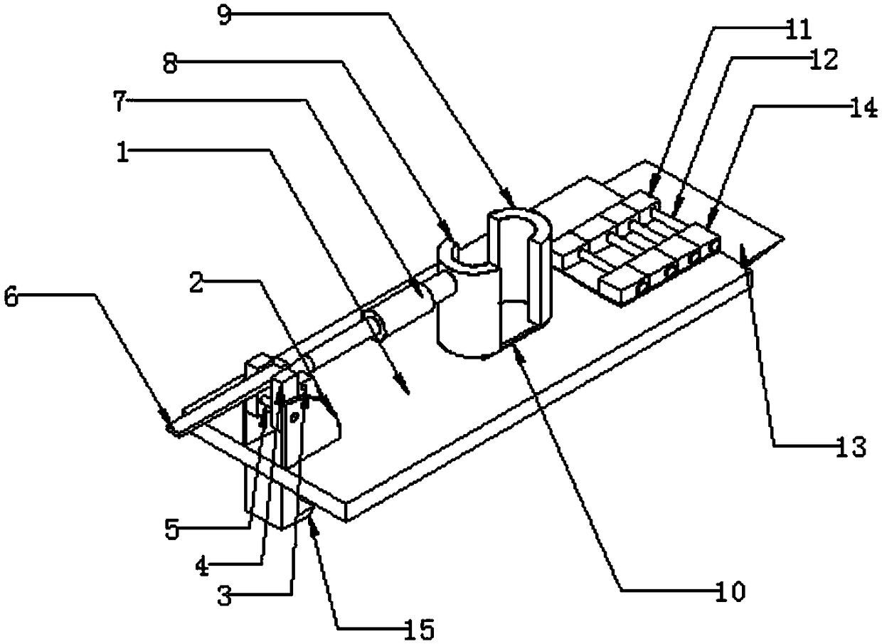
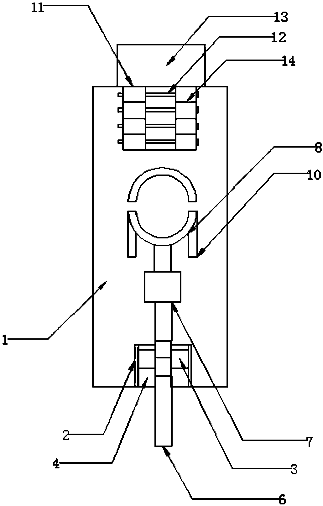
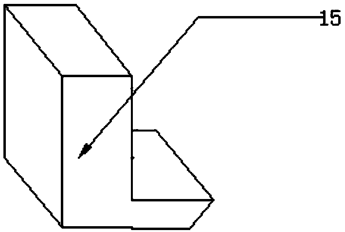
[0017] see Figure 1-3 , the present invention provides a technical solution: a mechanical fixture, including a fixture main body 1, a first fixing plate 2, a second rotating shaft 3, a second fixing plate 4, a first rotating shaft 5, a handle 6, a push rod 7, a second A rear splint 8, the first front splint 9, the first chute 10, the second left splint 11, bolt 12, wedge plate 13, the second right splint 14 and positioning plate 15, the top side of the fixtur...


PUM


Abstract

The invention discloses a mechanical clamp. The mechanical clamp comprises a clamp main body. A first fixing plate is arranged at one side of the top of the clamp main body. A second fixing plate is movably connected with the first fixing plate through a first rotating shaft. A handle is arranged at the inner side of the second fixing plate. A push rod is movably connected with the second fixing plate through a second rotating shaft. A first rear clamping plate is arranged at one end of the push rod. A first front clamping plate is arranged at the top of the clamp main body. A second left clamping plate is arranged at the other side of the top of the clamp main body. A second right clamping plate is fixed to the second left clamping plate through bolts. The first rear clamping plate is ina hollow semi-cylinder shape and is movably connected to the clamp main body through a first sliding groove. The circle center of the first rear clamping plate is located on a transverse central lineof the clamp main body. The first rear clamping plate can slide forwards and backwards through the push rod. The required fixation width can be adjusted conveniently; in addition, the cylindrical outer surface is smooth; and higher safety and reliability are achieved.

Description

technical field [0001] The invention relates to the technical field of mechanical clamps, in particular to a mechanical clamp. Background technique [0002] Fixtures are mainly used for workpiece fixing or clamping. When processing traditional mechanical parts, in order to improve production efficiency and ensure product quality, there are corresponding fixtures designed. The traditional fixture structure is single, and it is necessary to fix the fixture through additional workpieces to achieve workpiece. Fixing, generally speaking, different fixtures need to be used for different devices. [0003] The clamping parts of the fixtures in the prior art are not easy to replace, and only a single workpiece can be clamped. When processing small batches of multiple types of workpieces, it is inconvenient to replace the fixtures. Different fixtures need to be designed and manufactured for different workpieces, and the fixtures are universal. The performance is poor, and the fixture...

Claims


Application Information

Patent Timeline
Patent Type & Authority Applications(China)
IPC IPC(8): B25B11/00
CPCB25B11/00
Inventor 吴敏
Owner 吴敏
Why Eureka
Try Eureka