Improved oil seal type mold

An improved, oil-sealing technology, used in household appliances, other household appliances, household components, etc., can solve the problems of unstable product quality, increased tearing difficulty, edge damage, etc., and achieves short curing time and high material utilization. , the effect of short production time

Active Publication Date: 2018-12-11
安徽宁国中鼎模具制造有限公司
View PDF13 Cites 3 Cited by
  • Summary
  • Abstract
  • Description
  • Claims
  • Application Information

AI Technical Summary

Problems solved by technology

[0002] like figure 1 As shown, the existing oil seal mold is a molded structure, with a total of 4 types, one of which adopts the flash cutting process, and the other 3 adopts the edge tearing design, which requires manual tearing of the flash after the subsequent process, which is low in efficiency and high in cost. The quality is unstable, and in order to ensure the tearing effect, the edge tearing groove is usually designed to be very close to the cavity, less than 0.1mm, and the cutting edge must be sharp, so that the flash can be easily torn, but in actual production, the distance between the mold During the period, there will be friction and collision between the mold and the production tool, which will cause damage to the edge and increase the difficulty of edge tearing

Method used


Image

  • Improved oil seal type mold
  • Improved oil seal type mold

Examples


Embodiment Construction

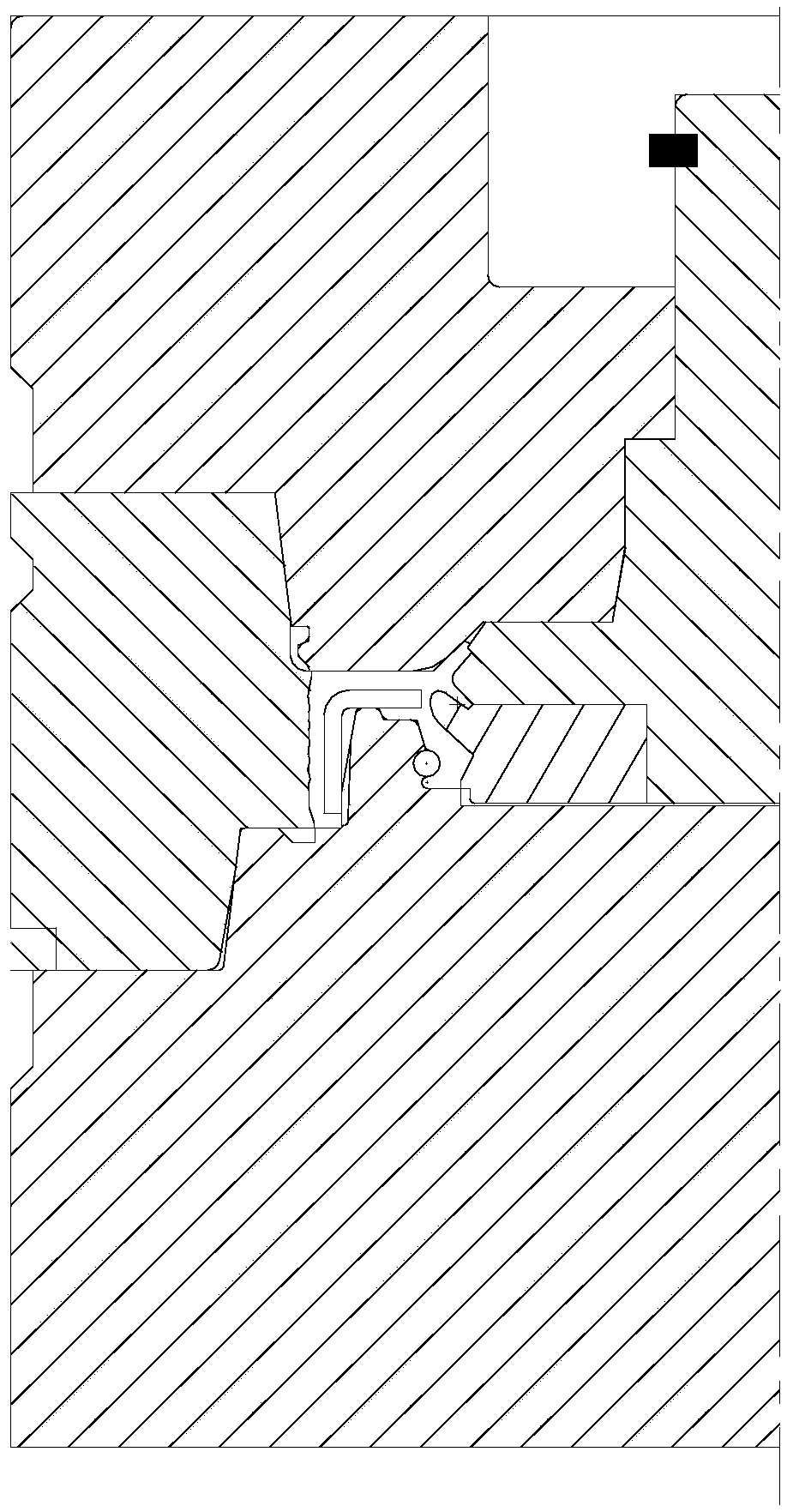
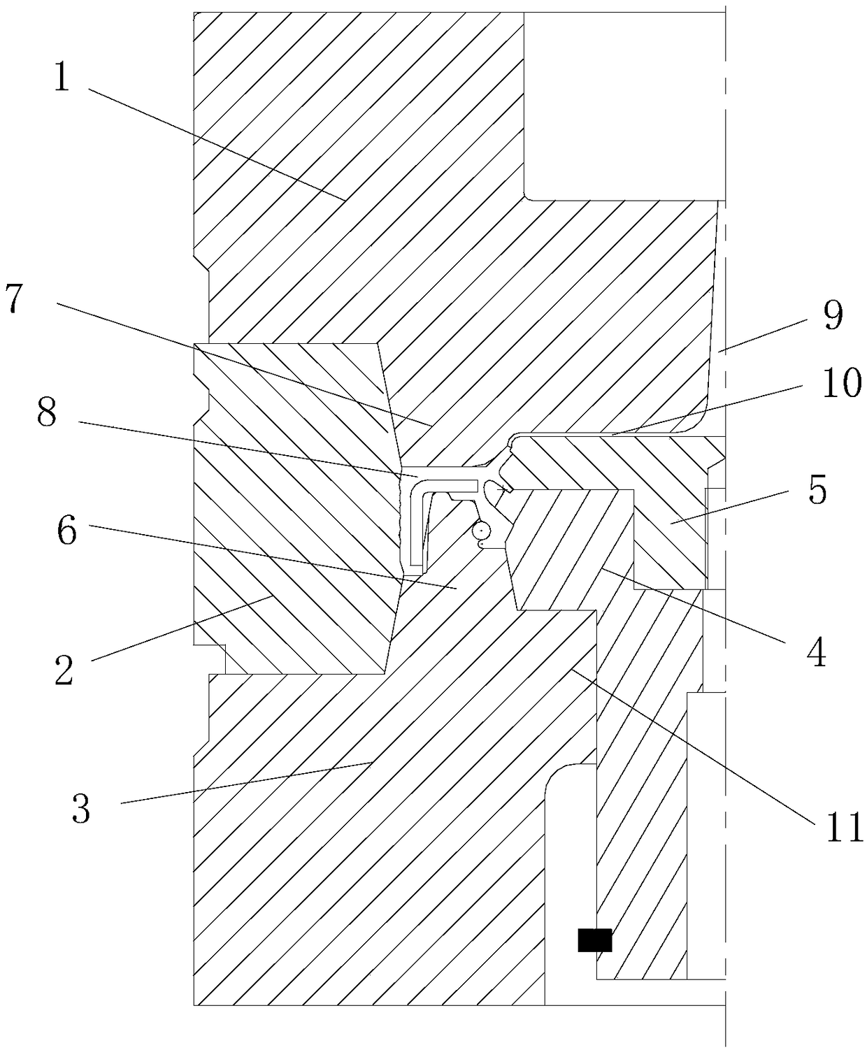
[0017] refer to figure 2 , the present invention proposes an improved oil seal type mold, including an upper mold 1 , a middle mold 2 , a lower mold 3 , a first mold core 4 and a second mold core 5 . The upper mold 1, the middle mold 2, and the lower mold 3 are arranged up and down. The middle mold 2 has a first mold cavity, and the top of the lower mold 3 is provided with an annular support platform 6 extending into the first mold cavity for supporting the oil seal skeleton. The mold core 4 is arranged in the first mold cavity and the bottom end of the first mold core 4 abuts against the lower mold 3 , the second mold core 5 is arranged in the first mold cavity and the second mold core 5 abuts against the first mold core 4 Rely, the bottom of the upper mold 1 is provided with an annular platform 7 extending into the first mold cavity. In the mold closing state, the upper mold 1, the middle mold 2, the lower mold 3, the first core 4, and the second core 5 A cavity 8 is forme...


PUM

PropertyMeasurementUnit
angleaaaaaaaaaa

Abstract

The invention provides an improved oil seal type mold, which comprises an upper mold, a middle mold, a lower mold, a first mold core and a second mold core, wherein the upper mold, the middle mold andthe lower mold are in vertical arrangement; the middle mold is provided with a first die cavity; the top end of the lower mold is provided with an annular support table which extends into the first die cavity and is used for supporting an oil seal framework; the first mold core is arranged in the first die cavity; the bottom end of the first mold core is abutted against the lower mold; the secondmold core is arranged in the first die cavity; the second mold core is abutted against the first mold core; the bottom end of the upper mold is provided with an annular table extending into the firstdie cavity; in the mold matching state, a die cavity is formed among the upper mold, the middle mold, the lower mold, the first mold core and the second mold core; the die cavity is communicated witha glue injection flow passage; a glue injection opening is formed in the upper mold; a glue injection flow passage for connecting the glue injection opening and the die cavity is formed between the upper mold and the second die cavity. The non-flash design and the flash cutting process are used; shaping is used in four parts; the non-flash design is used in three positions; only the flash in theglue inlet position need to be cut.

Description

technical field [0001] The invention relates to the technical field of oil seal molds, in particular to an improved oil seal mold. Background technique [0002] Such as figure 1 As shown, the existing oil seal mold is a molded structure, with a total of 4 types, one of which adopts the flash cutting process, and the other 3 adopts the edge tearing design, which requires manual tearing of the flash after the subsequent process, which is low in efficiency and high in cost. The quality is unstable, and in order to ensure the tearing effect, the edge tearing groove is usually designed to be very close to the cavity, less than 0.1mm, and the cutting edge must be sharp, so that the flash can be easily torn, but in actual production, the distance between the mold During this period, friction and collision will occur between the mold and the production tool, which will cause damage to the edge and increase the difficulty of edge tearing. Contents of the invention [0003] Based ...

Claims


Application Information

Patent Timeline
Patent Type & Authority Applications(China)
IPC IPC(8): B29C45/26B29C45/27B29L31/26
CPCB29C45/0025B29C45/26B29C45/27B29L2031/265
Inventor 郭继刚陈增宝韩双能喻家程马进孔文武王峰江佳勇
Owner 安徽宁国中鼎模具制造有限公司
Why Eureka
Try Eureka