
Ceiling lamp

A technology for ceiling lamps and lamp housings, applied in lighting devices, fixed lighting devices, electric light sources, etc., can solve the problems of inconvenient installation and replacement, and achieve the effect of convenient disassembly, convenient replacement and convenient installation

Pending Publication Date: 2018-12-11
SHAOXING LIANKONG PHOTOELECTRIC CO LTD
View PDF7 Cites 3 Cited by
  • Summary
  • Abstract
  • Description
  • Claims
  • Application Information

AI Technical Summary

Problems solved by technology

[0003] The purpose of the present invention is to provide a ceiling lamp, which has the advantages of being convenient for users to install and easy to replace when damaged, and solves the problems that it is inconvenient for users to install and inconvenient to replace when damaged

Method used


Image

  • Ceiling lamp
  • Ceiling lamp

Examples


Embodiment Construction

[0014] The following will clearly and completely describe the technical solutions in the embodiments of the present invention with reference to the drawings in the embodiments of the present invention.

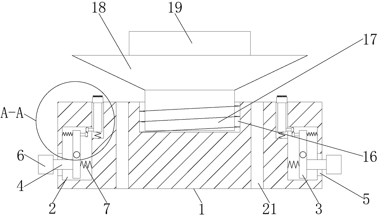
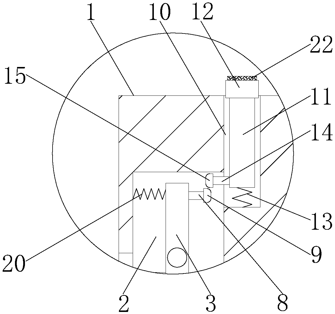
[0015] Such as Figure 1-2 , the present invention includes a base 1, the front of the base 1 is provided with a through hole 21, the through hole 21 is located on both sides of the threaded hole 16, through the through hole 21, it is convenient for the wiring harness on the ceiling lamp to pass through the base 1, so as to prevent the wiring harness from being incompatible with the The ceiling lamp is connected, and both sides of the front of the base 1 are provided with a first groove 2, and a movable rod 3 is movably connected to the first groove 2 through a rotating shaft, and the side of the movable rod 3 away from the second connecting rod 8 is fixedly connected to a second connecting rod 8. Three springs 20, the end of the third spring 20 away from the movable rod 3 is ...


PUM


Abstract

The invention discloses a ceiling lamp. The ceiling lamp comprises a base, two sides of the front face of the base are both provided with first grooves, each first groove is internally and movably connected with a moving rod through a rotating shaft, one end of each moving rod is fixedly connected with a first connection rod, the bottoms of two sides of the base are both provided with second grooves, and the second grooves communicate with the first grooves, and the end, away from the corresponding moving rod, of each first connection rod runs through the corresponding first groove and secondgroove in sequence and extends to the outer portion of the base to be fixedly connected with a clamping block. According to the ceiling lamp, by means of supporting blocks and supporting rods, the effect of driving second fixed blocks to move is achieved; by means of the second fixed blocks and first fixed blocks, the effect of driving the moving rods to move is achieved, and meanwhile, the effectof driving the clamping blocks to move is achieved; by means of first springs, the effect of supporting the clamping blocks is achieved; and by means of a threaded hole and a threaded rod, the effectof disassembling the ceiling lamp conveniently is achieved, the ceiling lamp is conveniently installed, and replacement is conveniently performed for users when the ceiling lamp is damaged.

Description

technical field [0001] The invention relates to the technical field of ceiling lamps, in particular to a ceiling lamp. Background technique [0002] Ceiling lamp is a kind of lighting and modern decorative lamp with noble grade. Its light source is a halide lamp cup. This light source has a strong decorative effect and is an ideal choice for modern high-light homes. It is very suitable for shopping malls and supermarkets. , hotels, jewelry counters and high-end homes, when the ceiling lamp is installed, it is generally to open a hole in the ceiling, and then use the driving power to snap the spring buckle on the ceiling lamp into the ceiling to fix the ceiling lamp, but this installation method It is inconvenient and inconvenient for users to install, and it is inconvenient for users to replace when damaged. Contents of the invention [0003] The object of the present invention is to provide a ceiling lamp, which is convenient for users to install and easy to replace when...

Claims


Application Information

Patent Timeline
Patent Type & Authority Applications(China)
IPC IPC(8): F21S8/04F21V19/04
CPCF21S8/04F21V19/04
Inventor 陈炎波
Owner SHAOXING LIANKONG PHOTOELECTRIC CO LTD
Learn More