Heating device for textile machinery

A heating device and textile machinery technology, applied in the field of textile machinery, can solve the problems of operator influence, temperature rise, cloth quality influence, etc., and achieve the effect of ensuring normal work.

Inactive Publication Date: 2018-12-11
FOSHAN SANCHUANG KNITTING CO LTD
View PDF8 Cites 0 Cited by
  • Summary
  • Abstract
  • Description
  • Claims
  • Application Information

AI Technical Summary

Problems solved by technology

[0002] In the weaving process, the cloth needs to be dried, and the device for drying the cloth in the prior art still has some disadvantages in actual use, such as a large amount of water vapor will be generated during drying, and the water vapor will enter the air and cause The temperature of the working environment will rise, which will affect the operator. At the same time, the fabric being operated will be heated to a higher temperature by the heating roller in an instant, which will affect the quality of the fabric.

Method used


Image

  • Heating device for textile machinery
  • Heating device for textile machinery
  • Heating device for textile machinery

Examples


Embodiment 1

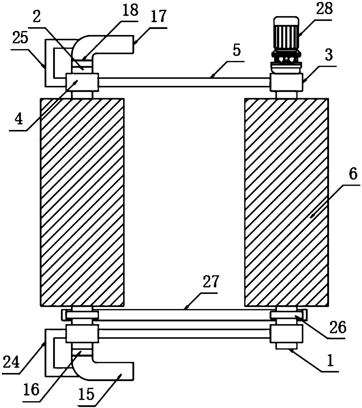
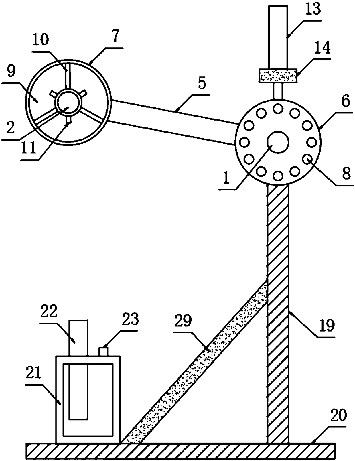
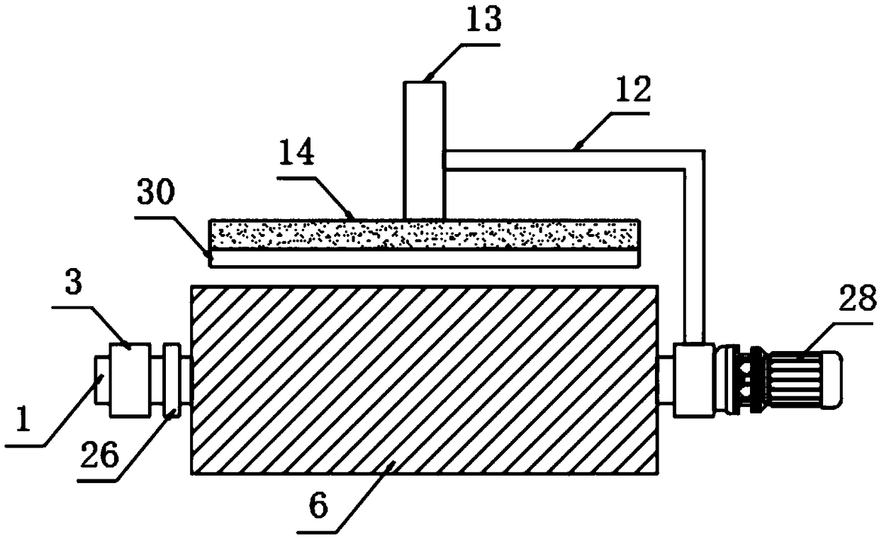
[0023] The present invention provides such Figure 1-3 The shown heating device for textile machinery includes a first rotating rod 1 and a second rotating rod 2, the second rotating rod 2 is arranged on one side of the first rotating rod 1, and the outer cover of the first rotating rod 1 The first heating roller 6 and the first fixing ring 3 are connected, and the heating resistor 8 is nested inside the first heating roller 6, and the second heating roller 7 and the second heating roller 7 are nested on the outside of the second rotating rod 2. Two fixed rings 4, the inside of the second heating roller 7 is provided with a gas storage chamber 9, the inside of the gas storage chamber 9 is provided with a support rod 10 and a gas transmission connection pipe 11, and the support rod 10 and the gas transmission connection pipe 11 Arranged in a staggered manner, the top of the first fixing ring 3 is provided with a first support frame 12 and the bottom is provided with a vertical ...

Embodiment 2

[0026] Further, in the above-mentioned embodiment 1, the first fixing ring 3 is arranged on both sides of the first heating roller 6, the second fixing ring 4 is arranged on both sides of the second heating roller 7, and the first fixing ring 3 and the second fixed ring 4 are fixedly provided with a connecting cross bar 5 .

[0027] Further, in the above-mentioned embodiment 1, a first bearing 16 is provided between the second air collecting pipe 15 and the second rotating rod 2, and a bearing 16 is provided between the second exhaust pipe 17 and the second rotating rod 2. The second bearing 18 .

[0028] Further, in the first embodiment above, the second air collecting pipe 15 is connected to the first air collecting pipe 13 through a pipe, and the second exhaust pipe 17 is connected to the first exhaust pipe 22 through a pipe.

[0029] Further, in the above-mentioned embodiment 1, the second support frame 24 and the third support frame 25 are fixedly provided on the side of...


PUM


Abstract

The invention discloses a heating device for textile machinery. The heating device for the textile machinery comprises a first rotating rod and a second rotating rod; the second rotating rod is arranged on one side of the first rotating rod; a first heating roller and first fixing rings sleeve the first rotating rod; heating resistors are nested in the first heating roller; a second heating rollerand second fixing rings sleeve the second rotating rod; a gas accommodating cavity is formed in the second heating roller; support rods and gas transmission connecting pipes are arranged in the gas accommodating cavity; the support rods and the gas transmission connecting pipes are alternately arranged; and each first fixing ring is provided with a first support frame at the top and a vertical rod at the bottom. The heating device for the textile machinery can effectively prevent the condition of the air temperature rising in working environments due to introduction of vapor into air, and prevents the influence on operators; and meanwhile, as the vapor is adopted to heat the gas accommodating cavity, and the gas accommodating cavity is used for preheating cloth, the influence on the clothquality by subsequent drying is reduced.

Description

technical field [0001] The invention relates to the technical field of textile machinery, in particular to a heating device for textile machinery. Background technique [0002] In the weaving process, the cloth needs to be dried, and the device for drying the cloth in the prior art still has some disadvantages in actual use, such as a large amount of water vapor will be generated during drying, and the water vapor will enter the air and cause The temperature of the working environment rises, thereby affecting the operator, and at the same time, the cloth being operated is heated to a higher temperature by the heating roller in an instant, which will affect the quality of the cloth. [0003] Therefore, it is necessary to invent a heating device for textile machinery to solve the above problems. Contents of the invention [0004] The purpose of the present invention is to provide a heating device for textile machinery, which collects and cools water vapor by using a water b...

Claims


Application Information

Patent Timeline
Patent Type & Authority Applications(China)
IPC IPC(8): F26B13/18F26B23/06F26B25/00
CPCF26B13/183F26B23/06F26B25/005
Inventor 罗建华
Owner FOSHAN SANCHUANG KNITTING CO LTD
Why Eureka
Try Eureka