Door-lifting type display cabinet

A display cabinet and door-type technology, which is applied in the field of lift-door refrigerated and frozen display cabinets, can solve the problems of dust and other sundries falling in, polluting food materials, poor performance, etc., and achieve the goal of improving energy efficiency, ensuring hygiene and health, and reasonable design Effect

Pending Publication Date: 2018-12-14
广东斯科曼制冷设备有限公司
View PDF0 Cites 1 Cited by
  • Summary
  • Abstract
  • Description
  • Claims
  • Application Information

AI Technical Summary

Problems solved by technology

[0002] At present, refrigerated display cabinets are commonly used fresh-keeping equipment in supermarkets and some restaurants. Most of the refrigerated cabinets on the market have a lift-door structure. If the door is flipped up, dust and other sundries will easily fall into the display cabinet through the gap, polluting the ingredients in the display cabinet and affecting food health
In order to solve this problem, some display cabinets with cover plates appear on the market. The cover plates on this type of display cabinets are of fixed structure, and when the cabinet door is closed, the top edge of the cabinet door and the cover plate are sealed. , but when the cabinet door is lifted, a gap will be formed between the cabinet door and the shielding cover. It enters the cabinet through the gap, which affects the quality of the food in the cabinet and cannot guarantee the hygiene and safety of the food.
[0003] In addition, the current lift-door refrigerated display cabinets are not very effective in airtightness and heat preservation due to their structure, so they can only provide refrigeration functions (the lowest temperature setting is about 4°C), but cannot provide refrigeration. function (the minimum setting temperature is about -25°C), this is because the performance of this type of display cabinet is too poor if it wants to achieve the freezing function

Method used


Image

  • Door-lifting type display cabinet
  • Door-lifting type display cabinet
  • Door-lifting type display cabinet

Examples


Embodiment Construction

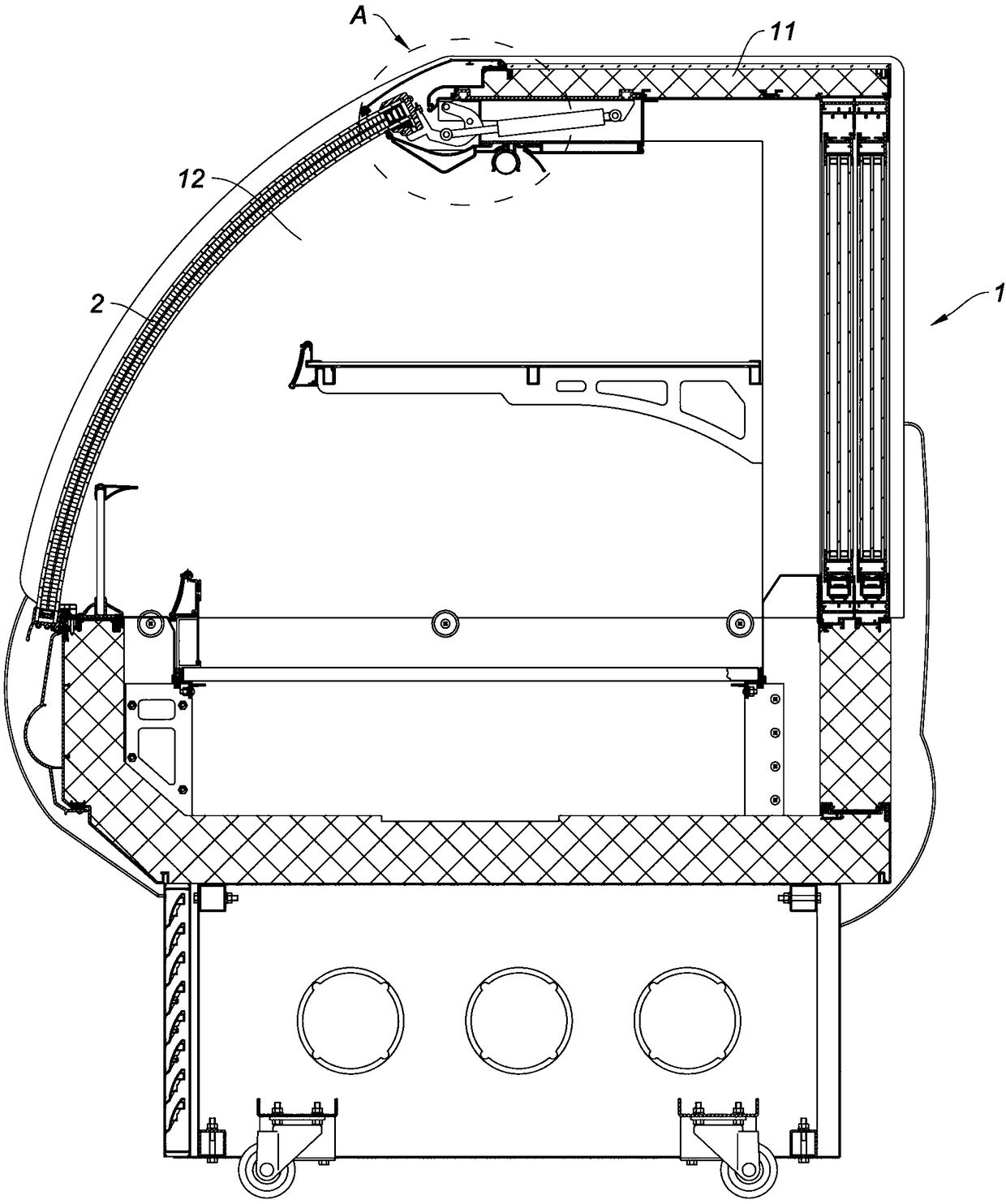
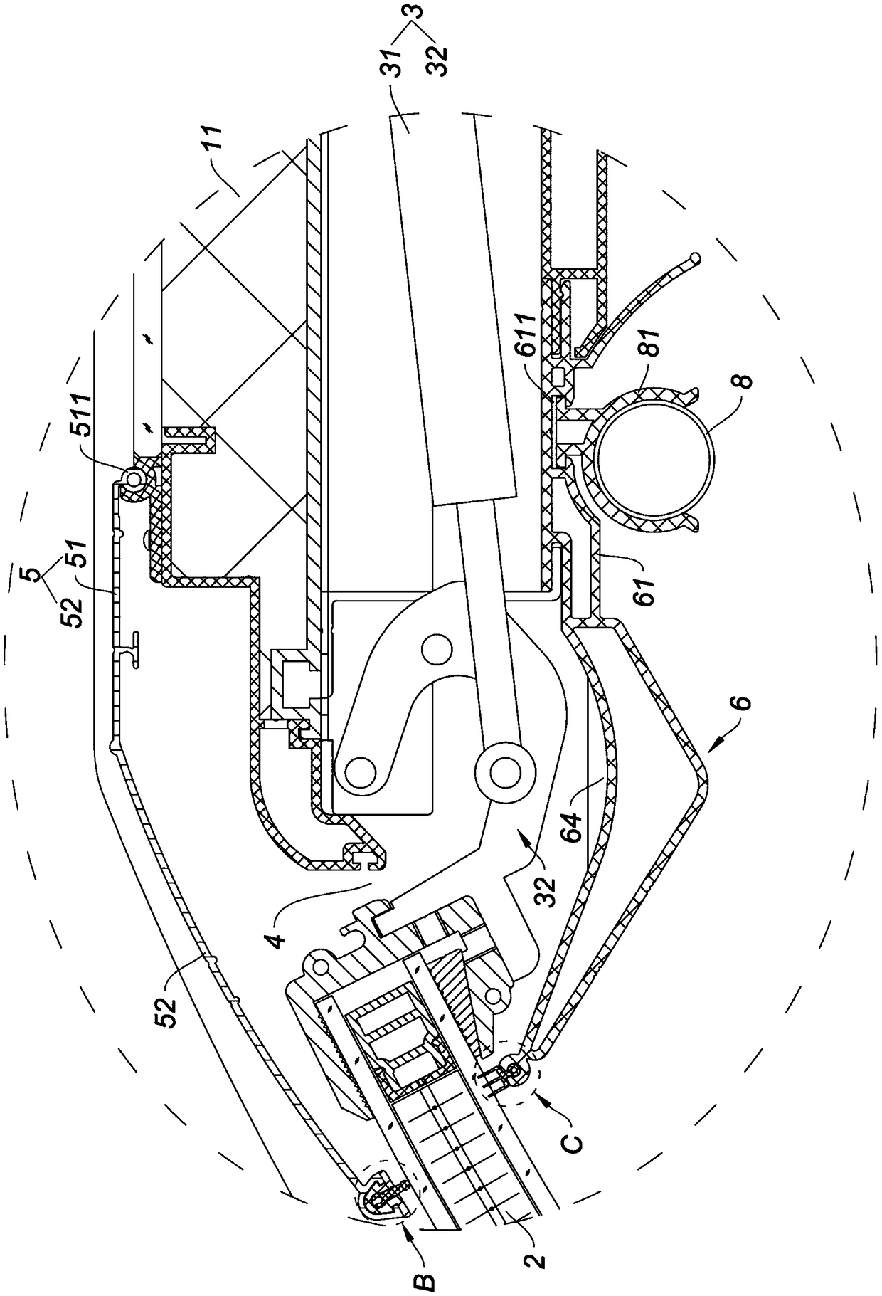
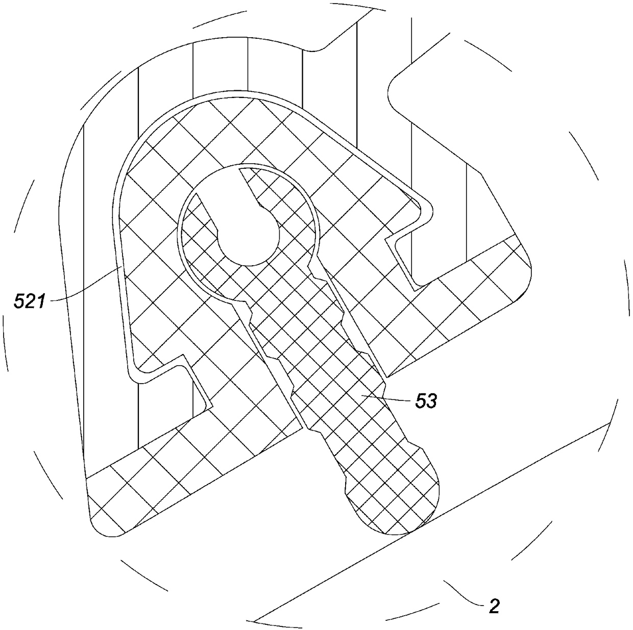
[0020] Such as figure 1 , figure 2 As shown, a lift-door display cabinet in this embodiment includes a cabinet body 1 and a cabinet door 2, the cabinet body 1 includes a top plate 11, and a cabinet door is formed on the front side of the cabinet body 1; the cabinet door 2. The cover is placed on the door of the cabinet. The cabinet door 2 and the cabinet body 1 are connected together by a support mechanism 3. The support mechanism 3 includes a damper 31 and a support arm 32. One end of the damper 31 is hinged to the top plate of the cabinet body 1. 11, the telescopic rod of the damper 31 is hinged with the middle part of the support arm 32, the upper part of the support arm 32 is hinged with the top plate 11, and the lower part of the support arm 32 is connected with the top edge of the cabinet door 2, at the top edge of the cabinet door 2 A gap 4 is formed between the top plate 11 of the cabinet body 1; a shielding cover 5 is also provided between the cabinet door 2 and the...


PUM


Abstract

The invention relates to a door-lifting type display cabinet. The door-lifting type display cabinet comprises a cabinet body and a cabinet door; the cabinet body comprises a top plate; a cabinet dooropening is formed in a front side of the cabinet body; the cabinet door covers the cabinet door opening; the cabinet door and the cabinet body are connected together through a supporting mechanism; agap is formed between a top edge of the cabinet door and the top plate of the cabinet body; a shielding cover plate is disposed between the cabinet door and the top plate; one side edge of the shielding cover plate is hinged to a top surface of the top plate, and the other side edge of the shielding cover plate is placed on an outer surface of the cabinet door, and in this way, the shielding coverplate can block the gap formed between the cabinet door and the top plate. The door-lifting type display cabinet is simple in structure, is reasonable in design, can block the gap formed between thecabinet door and the top plate during closing and opening of the cabinet door, can effectively ensure clean and healthy food in the cabinet body, can improve the energy efficiency level, and can prevent bacteria and pests.

Description

technical field [0001] The invention relates to the technical field of refrigerating and freezing equipment, in particular to a lift-door type refrigerating and freezing display cabinet. Background technique [0002] At present, refrigerated display cabinets are commonly used fresh-keeping equipment in supermarkets and some restaurants. Most of the refrigerated cabinets on the market have a lift-door structure. If the door is a swing-up type, dust and other sundries will easily fall into the display cabinet through the gap, polluting the ingredients in the display cabinet and affecting food health. In order to solve this problem, some display cabinets with cover plates appear on the market. The cover plates on this type of display cabinets are of fixed structure, and when the cabinet door is closed, the top edge of the cabinet door and the cover plate are sealed. , but when the cabinet door is lifted, a gap will be formed between the cabinet door and the shielding cover. E...

Claims


Application Information

Patent Timeline
Patent Type & Authority Applications(China)
IPC IPC(8): A47F5/00
CPCA47F5/00
Inventor 徐金阳徐金贤杨汉洲
Owner 广东斯科曼制冷设备有限公司
Why Eureka
Try Eureka