Instrument with multi-flow instrument head for argon plasma coagulation

An instrument and head technology, which is applied in the field of plasma coagulation instruments, can solve the problems of limited viewing angle and contamination of the tip of the instrument.

Active Publication Date: 2021-12-03
ERBE ELEKTROMEDIZIN GMBH
View PDF9 Cites 0 Cited by
  • Summary
  • Abstract
  • Description
  • Claims
  • Application Information

AI Technical Summary

Problems solved by technology

Furthermore, a clear view onto the treatment area may be limited due to shadows caused by the instrument
Furthermore, in close proximity there is an increased possibility of contaminating the tip of the instrument with tissue

Method used


Image

  • Instrument with multi-flow instrument head for argon plasma coagulation
  • Instrument with multi-flow instrument head for argon plasma coagulation
  • Instrument with multi-flow instrument head for argon plasma coagulation

Examples


Embodiment Construction

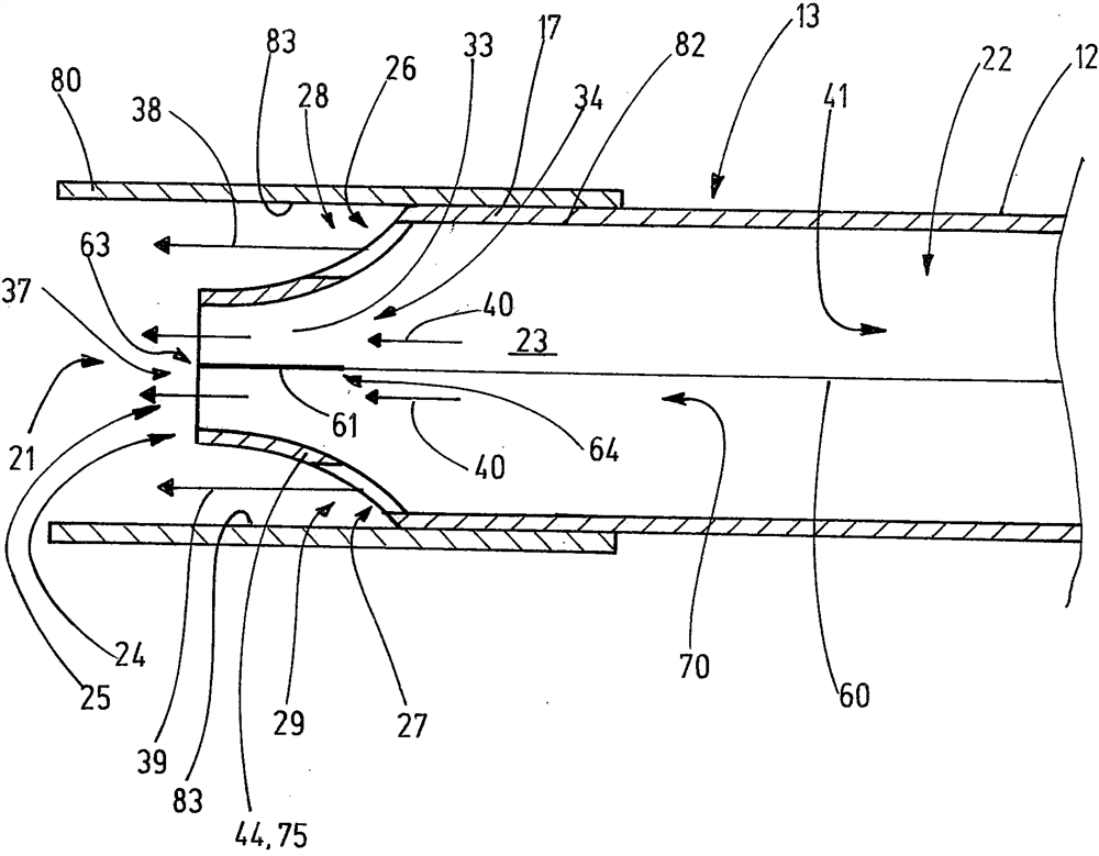
[0121] figure 1 The device 10 of the invention is shown in a side view of the instrument 13 with an endoscope and a gas supply line 12 of an electrosurgical instrument 13 of the invention in a cavity 14 of the patient's body (the gas supply line extending through through the working channel of the endoscope). Alternatively, the inventive instrument 13 can be guided externally on the endoscope 11, for example. Endoscopy 11 in figure 1 is shown, by way of example, with a distal end 16 which is curved with respect to the direction 15 of longitudinal expansion. The head 17 (instrument head) of the instrument 13 protruding from the working channel of the endoscope 11 forms the distal section of the instrument 13 . The instrument 13 is connected to a gas supply unit 18 (which is also figure 1 shown in ), and connected to RF generator 19.

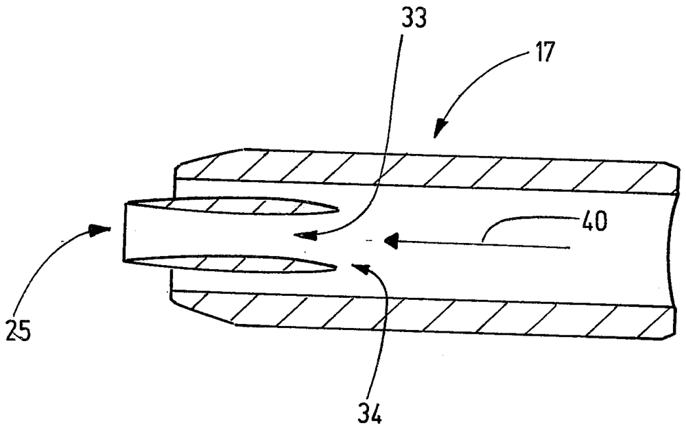
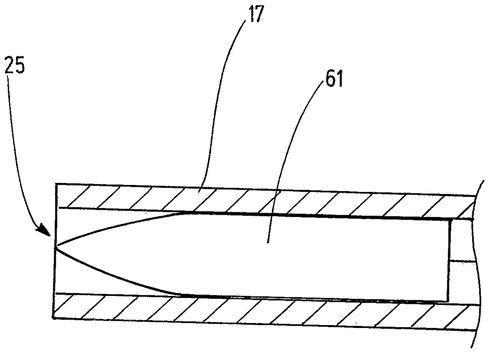
[0122] Figure 2a along with Figure 2b ) shows details of the electrosurgical instrument 13 with its head 17. Figure 2b Shown from the ...


PUM


Abstract

A new instrument for electrosurgical treatment. Includes instrument head. The instrument head forms a delivery body with a gas-fillable lumen. The lumen is connected to the first opening and the second opening in the instrument head. A primary flow of gas exits the instrument head through the first opening in a direction towards the tissue. The second opening is arranged relative to the first opening such that the secondary flow exits the second opening. The secondary flow surrounds the primary flow. Electrodes are arranged in the path of the gas flow out of the first opening for igniting the plasma. Due to the secondary flow arranged so as to accompany the primary flow, the ignition of the plasma is successful even if the instrument is at a relatively large distance from the tissue to be treated. Ignition of the plasma is successful at relatively large distances from the instrument to the tissue if the primary flow is formed as a core flow leaving the first opening and the secondary flow is formed as a surrounding flow leaving the second opening. The core flow and the surrounding flow are fed by the same lumen, so that the flows consist of the same gas.

Description

technical field [0001] The invention relates to an apparatus for argon plasma coagulation. Background technique [0002] In monopolar argon plasma coagulation (APC), the distal end of the instrument is brought near the tissue to be treated, and ionized argon gas is ignited between electrodes on the distal end of the instrument and the tissue surface, thereby serving as its The result is a plasma beam. With the use of a plasma beam it is possible to generate thermal tissue effects without contact between the distal end of the instrument and the tissue. Specifically, tissue failure or hemostasis may thus be achieved. Ignition distance refers to the distance the instrument needs to be moved into the tissue for successful ignition of the plasma to occur. [0003] Long ignition distances are desirable to ensure reliable ignition of the plasma, even at greater distances. The ignition distance should also be greater under the influence of reducing the ignition distance (for exa...

Claims


Application Information

Patent Timeline
Patent Type & Authority Patents(China)
IPC IPC(8): A61B18/00
CPCA61B18/042A61B2218/005A61B2018/00982A61B2017/00477A61B18/00A61B2018/00583A61B2018/00589H05H1/46A61B2018/048A61B2018/1253A61B18/082H05H1/4645
Inventor A.博德贝克C.阿提斯T.斯特贝勒
Owner ERBE ELEKTROMEDIZIN GMBH
Why Eureka
Try Eureka