
LED element automatic bending machine

An automatic bending machine and component technology, applied in the field of bending machines, can solve problems such as lack of LED pins and shaking of LED components, and achieve the effect of ensuring the bending effect and preventing shaking

Inactive Publication Date: 2018-12-14
肇庆高新区黑阳科技有限公司
View PDF0 Cites 2 Cited by
  • Summary
  • Abstract
  • Description
  • Claims
  • Application Information

AI Technical Summary

Problems solved by technology

[0004] The purpose of the present invention is to solve the problem that the bending machine in the prior art lacks a mechanism for fixing the LED pins, and in the process of bending the pins, it is easy to cause the LED components to shake, and a LED component is proposed. Automatic bending machine

Method used


Image

  • LED element automatic bending machine
  • LED element automatic bending machine

Examples


Embodiment Construction

[0016] The following will clearly and completely describe the technical solutions in the embodiments of the present invention with reference to the accompanying drawings in the embodiments of the present invention. Obviously, the described embodiments are only some, not all, embodiments of the present invention.

[0017] In describing the present invention, it should be understood that the terms "upper", "lower", "front", "rear", "left", "right", "top", "bottom", "inner", " The orientation or positional relationship indicated by "outside", etc. is based on the orientation or positional relationship shown in the drawings, and is only for the convenience of describing the present invention and simplifying the description, rather than indicating or implying that the referred device or element must have a specific orientation, so as to Specific orientation configurations and operations, therefore, are not to be construed as limitations on the invention.

[0018] refer to Figure ...


PUM


Abstract

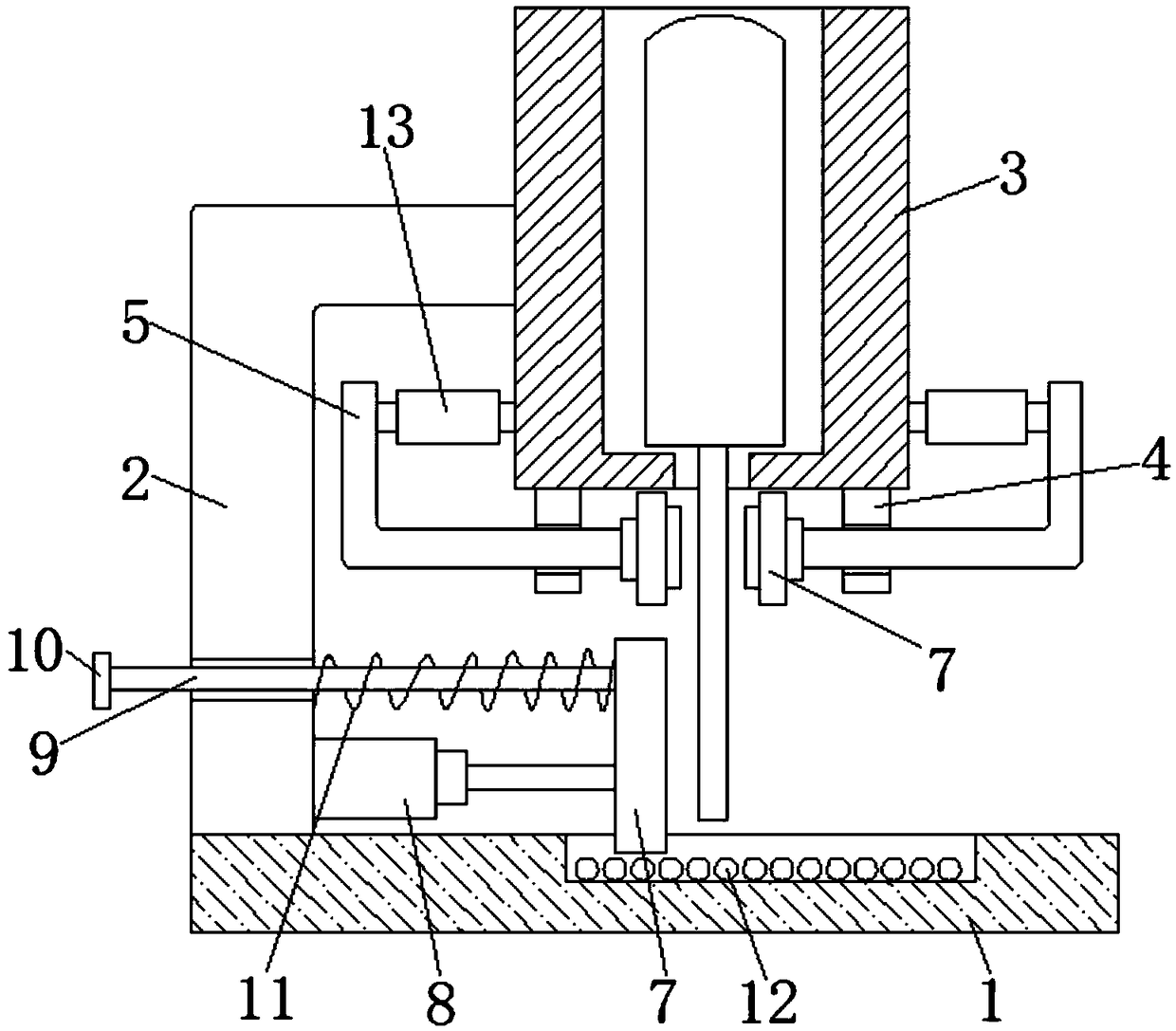
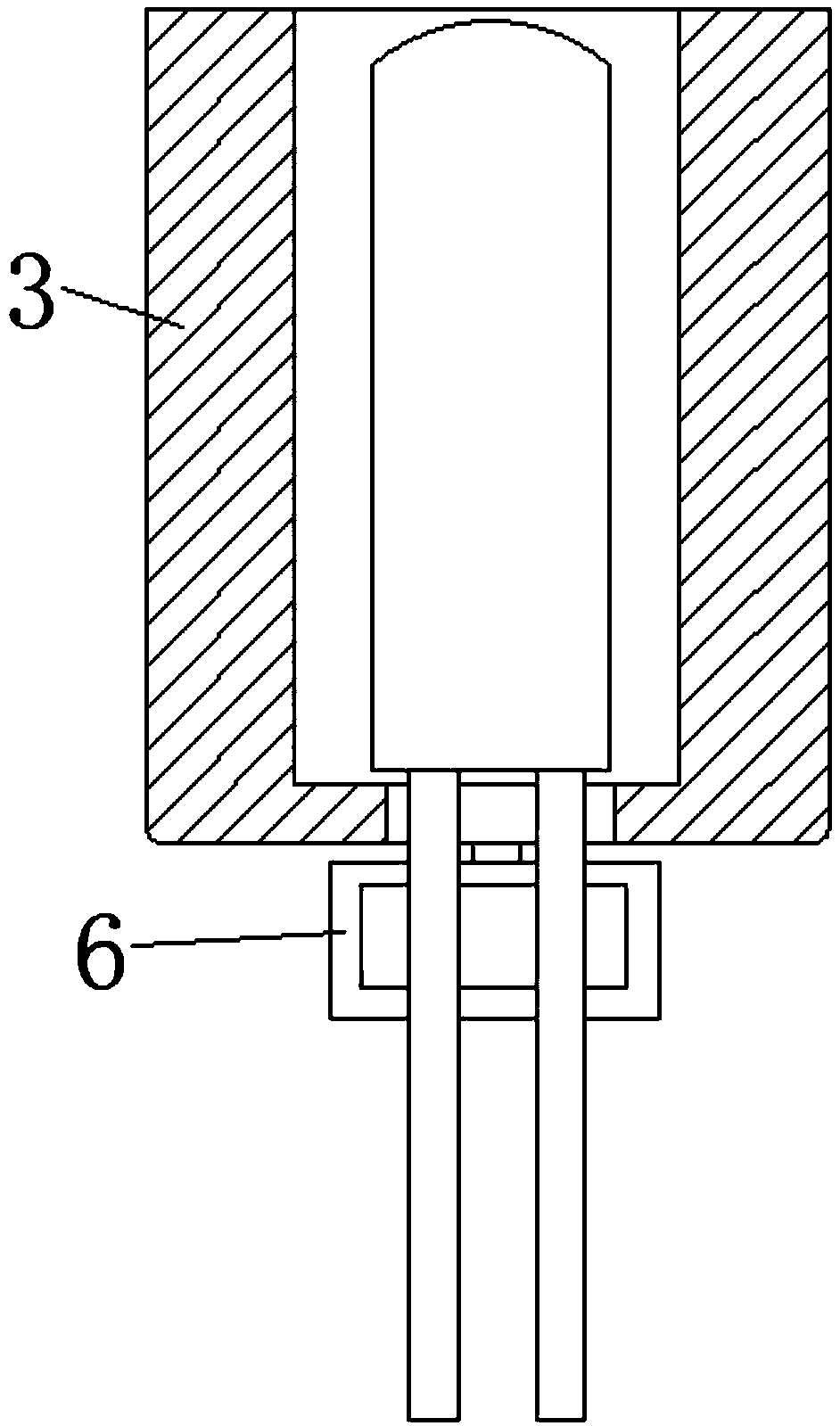
The invention discloses an LED element automatic bending machine. The LED element automatic bending machine comprises a base and a supporting column, the base is fixedly connected with the top of thesupporting column, a fixing sleeve is fixedly connected to the top of the supporting column, and a through hole is formed in the bottom of the fixing sleeve; two supporting blocks symmetrically arranged are fixedly connected to the bottom of the fixing sleeve, L-shaped clamping rods are arranged on the supporting blocks in a sliding mode, one ends, opposite to each other, of the two L-shaped clamping rods are fixedly connected with extrusion blocks, and one ends, far away from the extrusion blocks, of the L-shaped clamping rods are connected with the fixing sleeve through turnbuckles; and thebottom of one side, close to the fixing sleeve, of the supporting column is fixedly connected with a telescopic air cylinder, the output end of the telescopic air cylinder is fixedly connected with apushing plate, and a sliding groove corresponding to the pushing plate is formed in the top of the base. According to the LED element automatic bending machine, through the arrangement of the extrusion blocks, pins can be well fixed, so that an LED element can be effectively prevented from shaking, and the bending effect of the pins can be guaranteed.

Description

technical field [0001] The invention relates to the technical field of bending machines, in particular to an automatic bending machine for LED components. Background technique [0002] The pins of the original LED components are generally in-line, but the circuit board or product assembly design of some products requires that the pins of the LED be bent into a right angle or a Z shape. To fit the space of the circuit board or the shape of the product. For this reason, LEDs require secondary processing. [0003] However, the existing bending machine lacks a mechanism for fixing the LED pins. During the process of bending the pins, it is easy to cause the LED components to shake, thereby affecting the bending effect of the pins. Contents of the invention [0004] The purpose of the present invention is to solve the problem that the bending machine in the prior art lacks a mechanism for fixing the LED pins, and in the process of bending the pins, it is easy to cause the LED...

Claims


Application Information

Patent Timeline
Patent Type & Authority Applications(China)
IPC IPC(8): B21F1/00
CPCB21F1/004
Inventor 周维叶
Owner 肇庆高新区黑阳科技有限公司
Learn More