
Driving voltage control system and display device

A control system and driving voltage technology, applied in the direction of static indicators, instruments, etc., can solve the problems of charging differences and high costs of large-size display screens, and achieve the effect of low cost and reducing charging differences

Active Publication Date: 2021-11-30
HKC CORP LTD +1
View PDF0 Cites 0 Cited by
  • Summary
  • Abstract
  • Description
  • Claims
  • Application Information

AI Technical Summary

Problems solved by technology

[0004] Based on this, it is necessary to provide a driving voltage control system and a display device for the problems of charging differences and high cost of large-size display screens

Method used


Image

  • Driving voltage control system and display device
  • Driving voltage control system and display device
  • Driving voltage control system and display device

Examples


Embodiment Construction

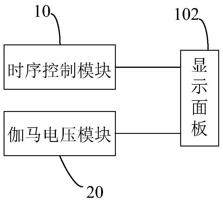
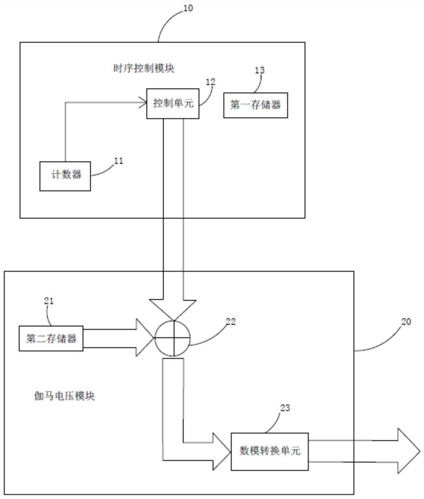
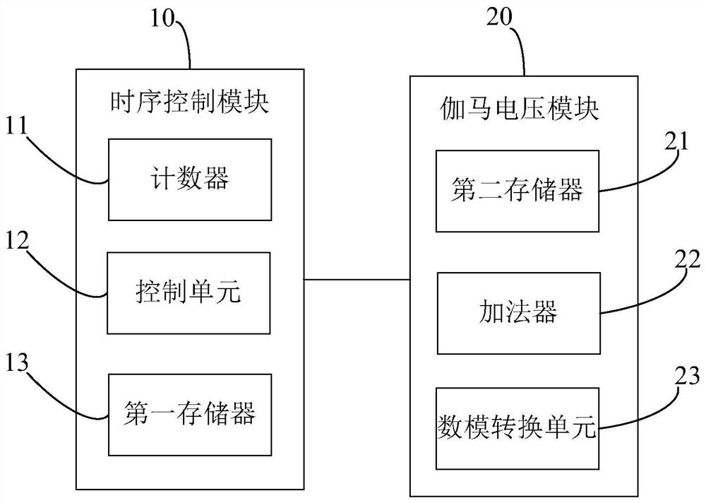
[0032] see figure 1 , the driving voltage control system includes: a timing control module 10 and a gamma voltage module 20 . The timing control module 10 is connected to the gamma voltage module 20 . The timing control module 10 is used to detect the current charging area of ​​the display panel 102 , and transmit the corresponding voltage difference data code to the gamma voltage module 20 according to the detected current charging area. The gamma voltage module 20 is configured to output a gamma voltage according to the voltage difference data code and the reference voltage data code to charge the display panel 102 . The display panel 102 is connected to the timing control module 10 and the gamma voltage module 20 .

[0033] The timing control module 10 is connected to the gamma voltage module 20 through a serial bus. In this embodiment, the timing control module 10 and the gamma voltage module 20 are connected through an I2C (Inter-Integrated Circuit) bus. In the commun...


PUM


Abstract

The invention relates to a driving voltage control system, comprising: a timing control module and a gamma voltage module; the timing control module is connected to the gamma voltage module; the timing control module is used to detect the current charging area of ​​the display panel, and transmit the current charging area The corresponding voltage difference data code is sent to the gamma voltage module; the gamma voltage module is used to output the gamma voltage according to the voltage difference data code and the reference voltage data code to charge the display panel. The driving voltage control system of the present invention can realize the charging effect of dynamic matching on the display panel, reduce the charging difference of the display panel, do not need to double the data lines, and have low cost.

Description

technical field [0001] The invention relates to the field of display technology, in particular to a driving voltage control system and a display device. Background technique [0002] As the size of the display becomes larger and the resolution becomes higher and higher, when the data line is charging the display panel, the charging difference between the near-end area of ​​the display panel close to the driver board and the far-end area away from the driver board becomes larger. It is more and more obvious that the near-end area of ​​the display panel close to the driver board has better charging effect and higher brightness, while the far-end area of ​​the display panel away from the driver board has poorer charging effect and lower brightness. [0003] At present, larger-sized display screens are usually charged by double-sided driving of data lines to reduce charging differences, but this method requires twice as many data lines and is expensive. Contents of the inventi...

Claims


Application Information

Patent Timeline
Patent Type & Authority Patents(China)
IPC IPC(8): G09G3/36G09G3/3208
CPCG09G3/3208G09G3/3696
Inventor 王明良
Owner HKC CORP LTD
Learn More