
Pixel drive control method, drive control circuit, display panel and storage medium

A pixel drive circuit, drive control circuit technology, applied in the field of pixel drive control methods, display panels and storage media, and drive control circuits, can solve problems such as charging differences, improve image quality, improve user experience, and reduce charging differences Effect

Inactive Publication Date: 2021-04-27
HEFEI BOE OPTOELECTRONICS TECH +1
View PDF10 Cites 0 Cited by
  • Summary
  • Abstract
  • Description
  • Claims
  • Application Information

AI Technical Summary

Problems solved by technology

[0005] In view of the shortcomings of the existing methods, the present application proposes a pixel driving control method, a driving control circuit, a display panel and a storage medium to solve the technical problem that charging differences are prone to occur in the Z-inversion driving method

Method used


Image

  • Pixel drive control method, drive control circuit, display panel and storage medium
  • Pixel drive control method, drive control circuit, display panel and storage medium
  • Pixel drive control method, drive control circuit, display panel and storage medium

Examples


Embodiment Construction

[0030] The present application is described in detail below, and examples of embodiments of the present application are shown in the drawings, wherein the same or similar reference numerals represent the same or similar components or components having the same or similar functions throughout. Also, detailed descriptions of known technologies will be omitted if they are not necessary to illustrate the features of the present application. The embodiments described below by referring to the figures are exemplary only for explaining the present application, and are not construed as limiting the present application.

[0031] Those skilled in the art can understand that, unless otherwise defined, all terms (including technical terms and scientific terms) used herein have the same meanings as commonly understood by those of ordinary skill in the art to which this application belongs. It should also be understood that terms, such as those defined in commonly used dictionaries, should ...


PUM


Abstract

Embodiments of the present application provide a pixel driving control method, a driving control circuit, a display panel, and a storage medium. The pixel driving control method includes: generating a driving control signal according to the display data of the sub-pixels in the target column and the target display brightness; the driving control signal includes sub-driving control signals with at least two duty ratios; and controlling the output of the pixel driving circuit according to the driving control signal. The corresponding pixel driving signal; the pixel driving signal includes sub-driving signals of at least two duty ratios. In the embodiment of the present application, sub-pixels in different rows can be driven by signals with different duty ratios, and then the charging time of sub-pixels in different rows can be adjusted, so as to reduce the charging of sub-pixels in each row caused by the same charging time. difference, so that the display brightness of each row of sub-pixels tends to be consistent, thereby improving image quality and user experience.

Description

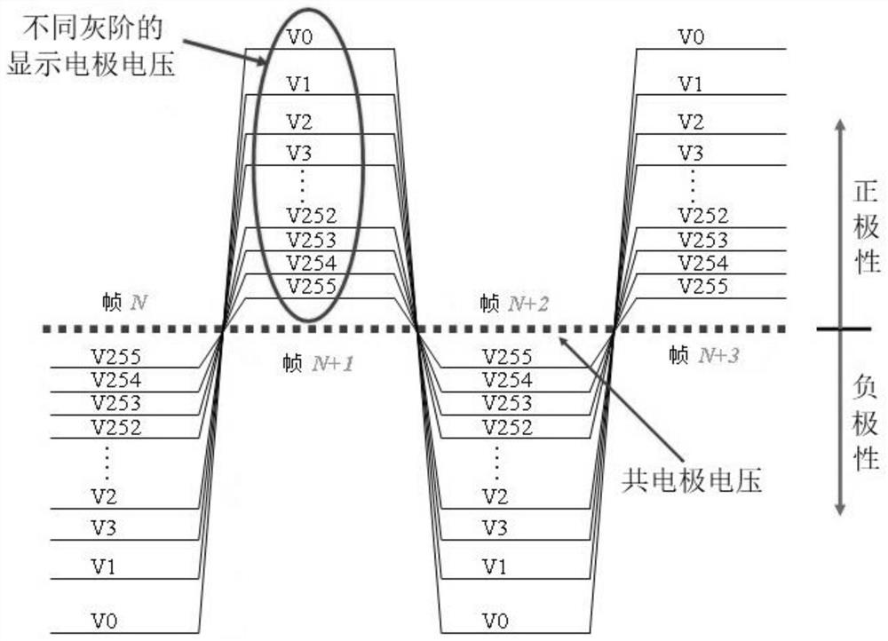
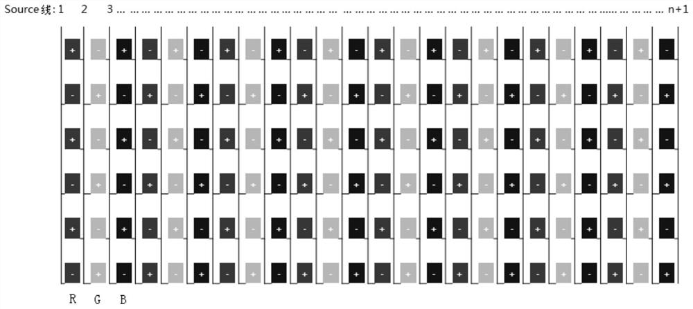
technical field [0001] The present application relates to the field of display technology, and in particular, the present application relates to a pixel driving control method, a driving control circuit, a display panel and a storage medium. Background technique [0002] The charging time of each row of pixels in the conventional driving method is the same, but for Z inversion, by figure 2 It can be seen that Z inversion (Z-Inversion or Z Dot Inversion) in a specific screen is prone to the charging difference between lines and horizontal stripes. [0003] TFT-LCD (Thin Film Transistor-Liquid Crystal Display, Thin Film Transistor-Liquid Crystal Display) will charge each pixel when it is working, so as to realize the display function of the pixel. In an ideal TFT-LCD driving model, the driving signal is symmetrically distributed based on the common electrode voltage Vcom, and the voltage of the display electrode is also symmetrically distributed based on Vcom, forming a fig...

Claims


Application Information

Patent Timeline
Patent Type & Authority Patents(China)
IPC IPC(8): G09G3/36
CPCG09G3/3688G09G3/3614G09G3/3648G09G2320/0204G09G2320/0219G09G2320/0223G09G2310/02H01L27/124
Inventor 李琨曹杰张月圆孙辉
Owner HEFEI BOE OPTOELECTRONICS TECH
Learn More