
Scanning signal generation method and device, display device

A technology for scanning signals and generating devices, which is applied to static indicators, instruments, etc., and can solve the problems of increased brightness and flickering of light-emitting elements OLED displays

Active Publication Date: 2019-10-11
BOE TECH GRP CO LTD +1
View PDF9 Cites 0 Cited by
  • Summary
  • Abstract
  • Description
  • Claims
  • Application Information

AI Technical Summary

Problems solved by technology

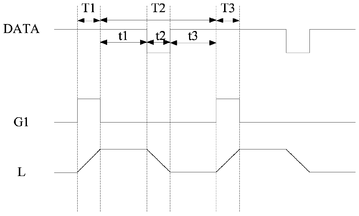
In the next charging stage (that is, the T3 time period), since the first scanning signal G1 is at a high level, the first switching transistor T1 is turned on, and the capacitor C is recharged, resulting in an increase in the display brightness L of the electroluminescent element OLED, thereby appearing splash screen phenomenon

Method used


Image

  • Scanning signal generation method and device, display device
  • Scanning signal generation method and device, display device
  • Scanning signal generation method and device, display device

Examples


Embodiment Construction

[0060] Example embodiments will now be described more fully with reference to the accompanying drawings. However, the example embodiments can be implemented in various forms, and should not be construed as being limited to the embodiments set forth herein; on the contrary, these embodiments are provided so that this disclosure will be comprehensive and complete, and fully convey the concept of the example embodiments To those skilled in the art. The described features, structures or characteristics may be combined in one or more embodiments in any suitable manner. In the following description, many specific details are provided to give a sufficient understanding of the embodiments of the present disclosure. However, those skilled in the art will realize that the technical solutions of the present disclosure can be practiced without one or more of the specific details, or other methods, components, materials, devices, steps, etc. can be used. In other cases, well-known technic...


PUM


Abstract

The present invention provides a scanning signal generation method and device, and a display device, and applied to the display technology field. The method comprises: providing conduction signals; providing turn-off signals, wherein the turn-off signals are controlled to jump to a preset voltage according to the type of a switching transistor in the black insertion phase of a pixel driving circuit; and generating scanning signals according to the conduction signals and the turn-off signals. In the black insertion phase, the turn-off signals are jumped to the preset voltage in a preset mode according to the type of the switching transistor so that even if the threshold voltage of the switching transistor generates negative drifting, the turn-off signals after jumping can turn off the switching transistor after the threshold voltage generates negative drifting to prevent charges in a capacitor from electric leakage through the switching transistor, allow the display brightness of electroluminescent cells to be consistent and avoid generation of cross color and splash screen phenomenons.

Description

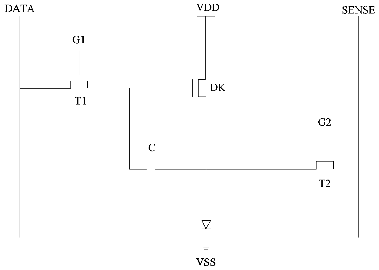
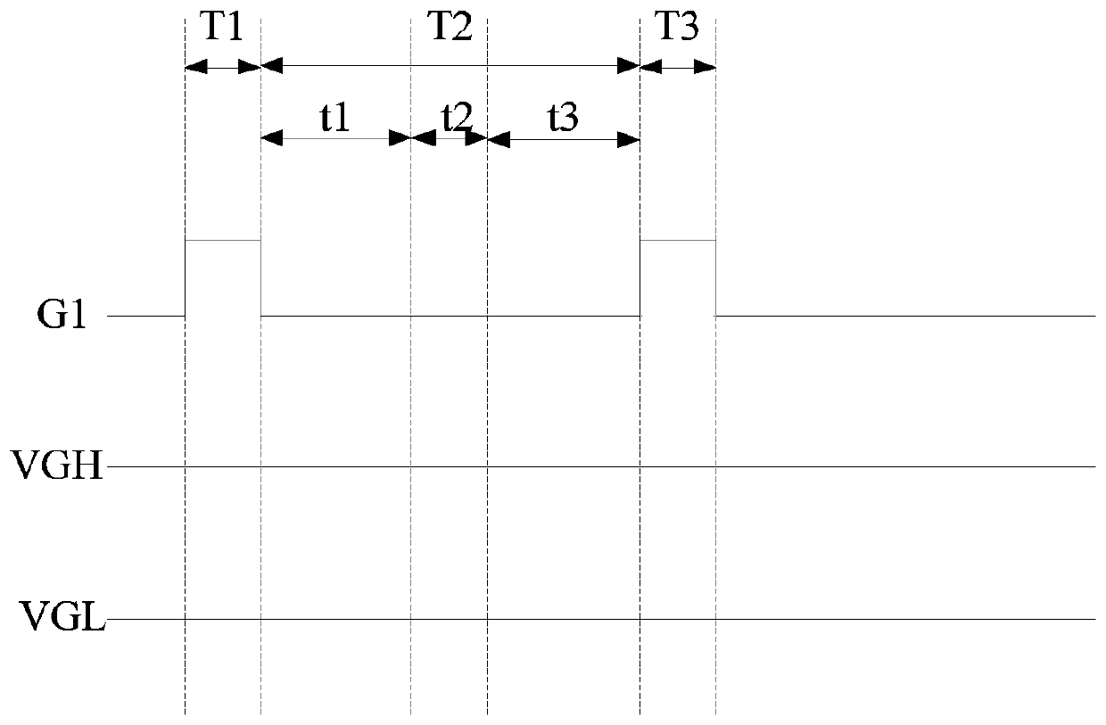
Technical field [0001] The present disclosure relates to the field of display technology, and in particular to a scanning signal generation method and device, and a display device. Background technique [0002] In display driving technology, scan lines and data lines intersect to form an active matrix. Wherein, the scan line is used to provide a scan signal to the switch transistor in the pixel drive circuit to control the on and off of the switch transistor, and the data line is used to provide a data signal to the pixel drive circuit. [0003] At present, the scan signal on the scan line is usually generated according to the working phase of the pixel driving circuit and combined with a turn-on signal with a constant voltage and a turn-off signal with a constant voltage. To figure 1 The pixel driving circuit shown in, and the transistors in the pixel driving circuit are all N-type transistors as an example, the process of generating the first scan signal G1 in the pixel driving ...

Claims


Application Information

Patent Timeline
Patent Type & Authority Patents(China)
IPC IPC(8): G09G3/3208
Inventor 鲍文超徐海侠李恒
Owner BOE TECH GRP CO LTD
Learn More