
Source driver, driving system, liquid crystal display device and correction method thereof

A technology of a liquid crystal display device and a source driver, which is applied in the direction of instruments, static indicators, optics, etc., and can solve problems such as enlargement, different liquid crystal deflection angles, and reduced display effect of the liquid crystal display panel 1

Active Publication Date: 2021-02-23
BOE TECH GRP CO LTD +1
View PDF7 Cites 0 Cited by
  • Summary
  • Abstract
  • Description
  • Claims
  • Application Information

AI Technical Summary

Problems solved by technology

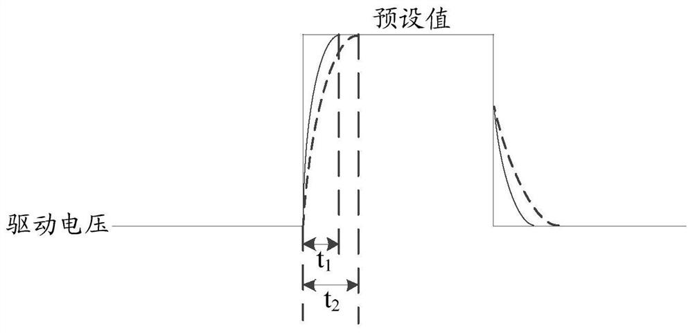
The reason why t2 is greater than t1 is that when there is light, the impedance of the active layer increases compared to when there is no light, resulting in a slow rise in the driving voltage
And t2 is greater than t1, which will lead to the charging time T-t1 of the sub-pixel when there is light relative to the charging time T-t when there is no light 2 becomes shorter, resulting in the problem of different sub-pixel charging rates
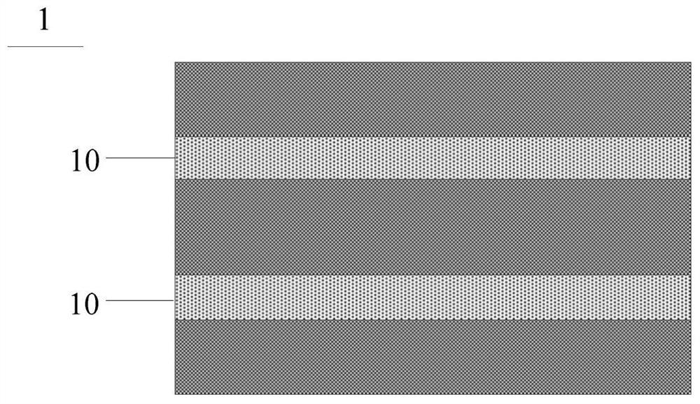
The different charging rates will lead to different deflection angles of the liquid crystal, and different display brightness of the sub-pixels, which will lead to the display of the LCD panel such as Figure 2 shows moving or stationary horizontal stripe pattern 10 (called water fall failure), water fall failure causes the entire liquid crystal display The display effect of panel 1 is greatly reduced
Especially when displaying a monochrome image, the water fall defect is more obvious

Method used


Image

  • Source driver, driving system, liquid crystal display device and correction method thereof
  • Source driver, driving system, liquid crystal display device and correction method thereof
  • Source driver, driving system, liquid crystal display device and correction method thereof

Examples


Embodiment Construction

[0066] The following will clearly and completely describe the technical solutions in the embodiments of the present invention with reference to the accompanying drawings in the embodiments of the present invention. Obviously, the described embodiments are only some, not all, embodiments of the present invention. Based on the embodiments of the present invention, all other embodiments obtained by persons of ordinary skill in the art without making creative efforts belong to the protection scope of the present invention.

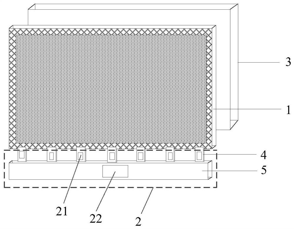
[0067] Such as image 3 As shown, the present invention provides a liquid crystal display device, including a liquid crystal display panel 1 , a driving system 2 and a backlight module 3 .

[0068] Such as Figure 4a As shown, the liquid crystal display panel 1 has a display area A and a peripheral area S, and the peripheral area S is arranged around the display area A, for example. The above-mentioned display area A includes multiple colors of sub-pixels (s...


PUM


Abstract

The invention provides a source driver, a driving system, a liquid crystal display device and a correction method thereof, relates to the technical field of display and can improve the display effectof the liquid crystal display device. The source driver comprises a plurality of driving units, wherein the driving unit is connected with a data input end, a data voltage output end and at least twocontrol ends; the driving unit is configured to output an analog data voltage through the data voltage output end according to a data signal input by the data input end; and moreover, under the control of the control signals input by the at least two control ends, the data voltage output end outputs different output impedances.

Description

technical field [0001] The invention relates to the field of display technology, in particular to a source driver, a driving system, a liquid crystal display device and a correction method thereof. Background technique [0002] Liquid Crystal Display (LCD) is widely used in modern information devices such as TVs, notebooks, computers, mobile phones, and personal digital assistants due to its small size, low power consumption, no radiation, and relatively low manufacturing costs. . [0003] The LCD generally includes a liquid crystal display panel and a backlight module that provides a light source for the liquid crystal display panel. The backlight module can emit light under the control of a PWM (pulse width modulation, pulse width modulation) signal. [0004] According to the PWM signal, the light emitted by the backlight module (that is, the light incident on the liquid crystal display panel) changes alternately between bright and dark at a certain frequency. That is, t...

Claims


Application Information

Patent Timeline
IPC IPC(8): G09G3/36
CPCG09G3/3685H05B45/325G02F1/13452G02F1/136286
Inventor 孙建伟周留刚戴珂韩屹湛熊玉龙李涛尹晓峰朱茂洋方鹏军
Owner BOE TECH GRP CO LTD
Learn More