
A tri-bar display panel

A display panel, grid technology, applied in static indicators, optics, instruments, etc., can solve problems such as color shift, and achieve the effect of reducing color shift, compressing height, and improving display quality

Active Publication Date: 2017-01-25
TCL CHINA STAR OPTOELECTRONICS TECH CO LTD
View PDF5 Cites 0 Cited by
  • Summary
  • Abstract
  • Description
  • Claims
  • Application Information

AI Technical Summary

Problems solved by technology

Therefore, the charging of the first subpixel charged is not as ideal as the second subpixel
Especially where the trace impedance in the fan-out area is the largest, that is, the difference in sub-pixel charging on both sides of the panel will cause color shift

Method used


Image

  • A tri-bar display panel
  • A tri-bar display panel
  • A tri-bar display panel

Examples


Embodiment Construction

[0025] The implementation of the present invention will be described in detail below in conjunction with the accompanying drawings and examples, so as to fully understand and implement the process of how to apply technical means to solve technical problems and achieve technical effects in the present invention. It should be noted that, as long as there is no conflict, each embodiment and each feature in each embodiment of the present invention can be combined with each other, and the formed technical solutions are all within the protection scope of the present invention.

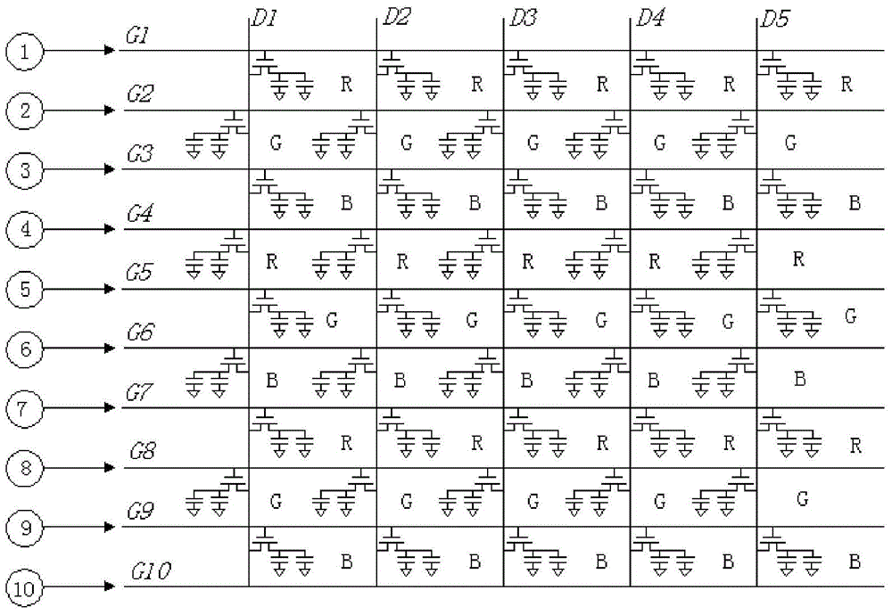
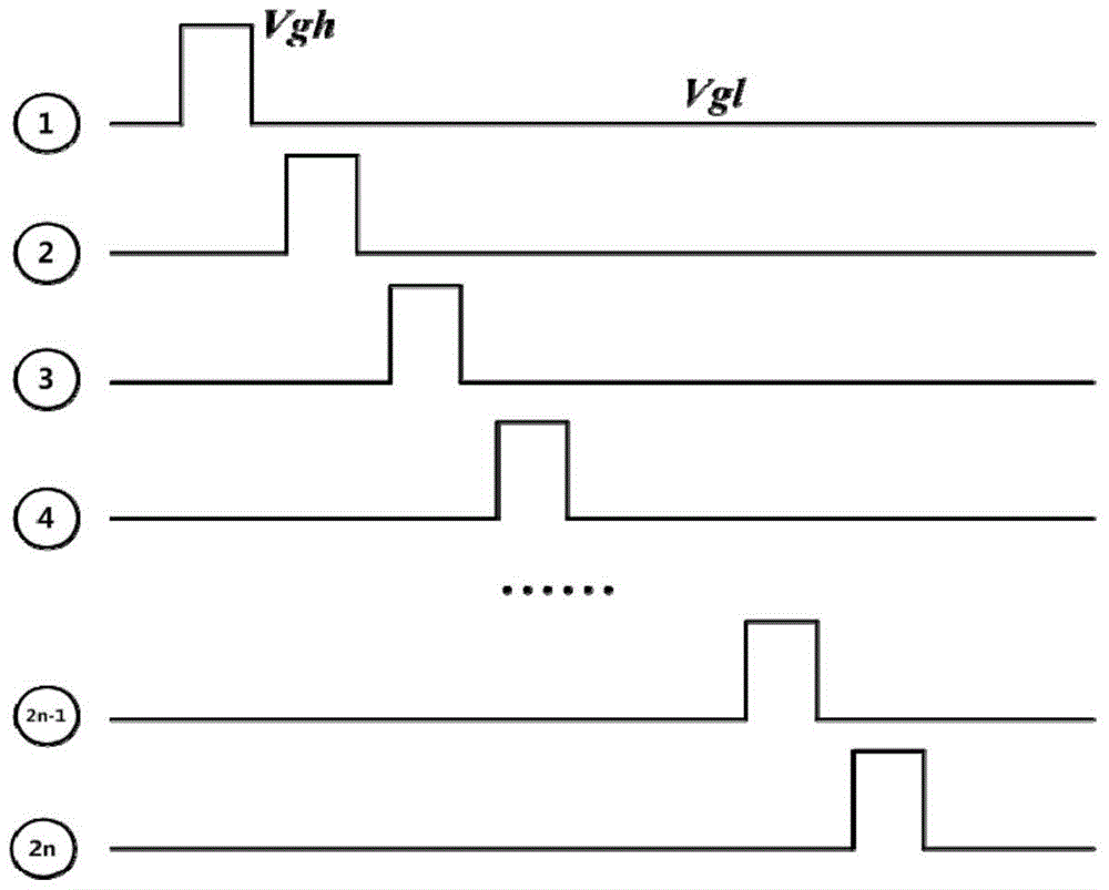
[0026] figure 1 A wiring diagram of fan-out terminals and pixel cells of a conventional tri-gate display panel with a high pin count design on the source side is shown. Among them, D1-D5 are data lines (Data Line), G1-G10 are scanning lines (GateLine), and the numbers in circles indicate the numbers of the fan-out area (Fanout) lines.

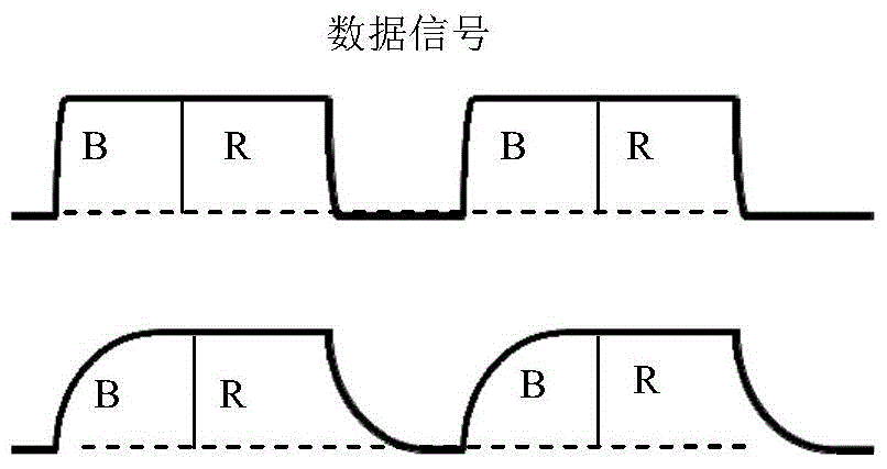
[0027] figure 2 shows the corresponding figure 1 The charging situat...


PUM


Abstract

The invention discloses a tri-gate display panel, which includes: a plurality of pixel units, including three sub-pixel units representing different colors. A thin film transistor is provided on each sub-pixel unit, and the source of the thin film transistor passes through the sub-pixel. The unit's own capacitance is connected to the charging electrode of each sub-pixel; the scanning lines are sequentially arranged along the first direction of the display panel to connect with the gates of each thin film transistor on the sub-pixel unit; the data lines are along the second direction of the display panel Set to be connected to the drain of the thin film transistor provided on the sub-pixel unit; the fan-out area includes a plurality of fan-out lines, the output ends of each fan-out line are aligned with the scan lines, and intersect with each scan line in pairs connect. The present invention reduces the charging difference of sub-pixels of different colors, thereby avoiding the color shift on both sides of the mixed-color picture and improving the display effect. At the same time, the restriction on the impedance of the source-side fan-out area during design is relaxed, which is beneficial to the design of narrow borders.

Description

technical field [0001] The present invention relates to the field of display technology, in particular to a tri-gate display panel. Background technique [0002] When designing a trigate display panel (Trigate Panel), traditionally, in order to save costs, the source side (source) often adopts a high pin count design. For example, only one set of fanout terminals (fanout) and one integrated circuit chip (IC) are used on the source side. However, the resistance difference (Rmax-Rmin) on the fan-out area designed in this way is generally relatively large. [0003] In actual work, the main problem caused by the large impedance difference of the fan-out area on the source side is that there is a color shift on both sides of the panel when displaying a mixed color picture. In the color mixing screen, the data line will continuously charge two sub-pixels, and then charge the two sub-pixels of the next pixel. Due to the large impedance of the fan-out area, the RC delay of the sig...

Claims


Application Information

Patent Timeline
Patent Type & Authority Patents(China)
IPC IPC(8): G09G3/20
CPCG09G3/20G09G3/3648G09G2310/0213G09G2320/0223G09G2320/0242G02F1/136G09G3/30H01L27/1214H01L27/124H01L27/1255H01L33/38
Inventor 杜鹏
Owner TCL CHINA STAR OPTOELECTRONICS TECH CO LTD
Learn More