Supercharge Your Innovation With Domain-Expert AI Agents!

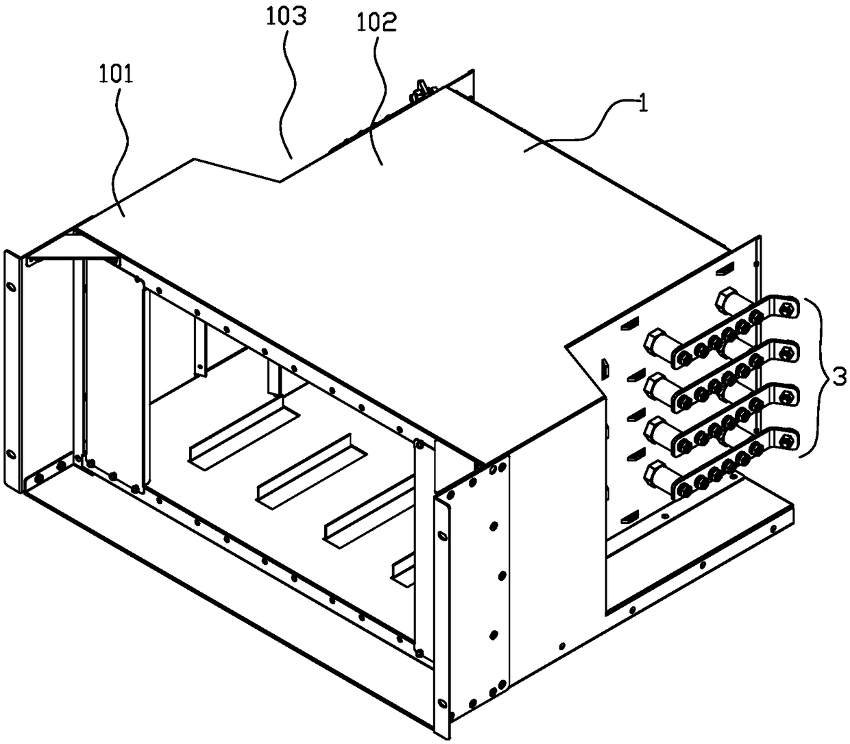
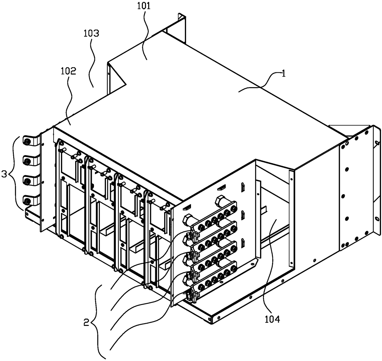
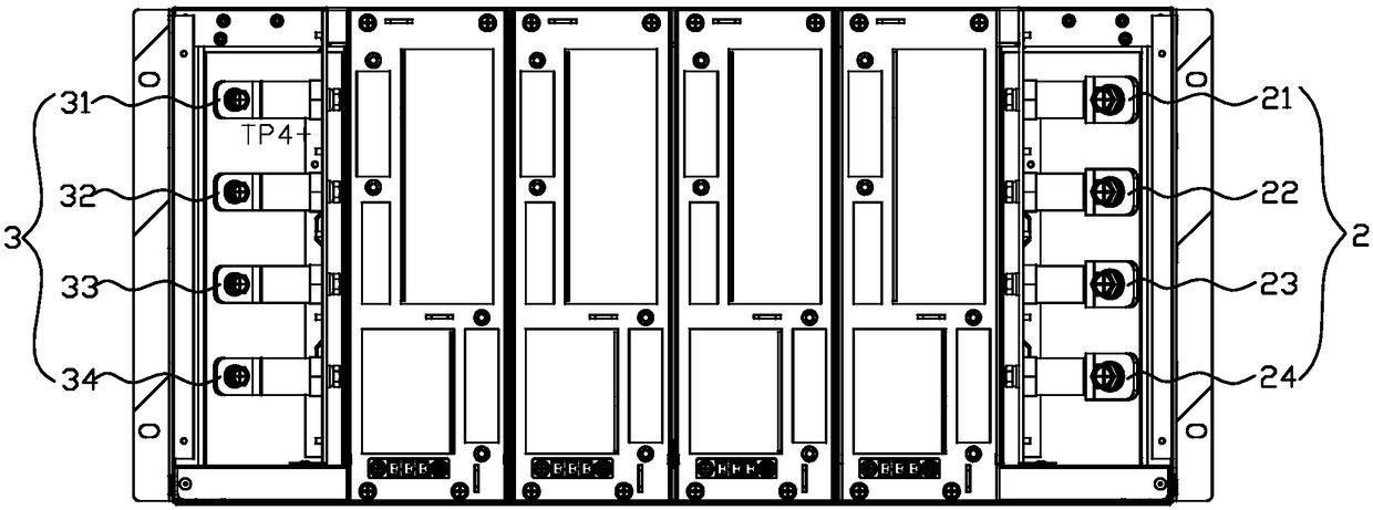
Charging module mounting structure and a charging machine

A charging module and installation structure technology, which is applied in the modification of power electronics, electric vehicle charging technology, electric vehicles, etc., can solve the problems of unfavorable wiring work of cables, affecting the performance and operation quality of the charging equipment, and avoid adverse effects. Effect

Active Publication Date: 2018-12-18
SHENZHEN CAR ENERGY NET CO LTD
View PDF6 Cites 1 Cited by
  • Summary
  • Abstract
  • Description
  • Claims
  • Application Information

AI Technical Summary

Benefits of technology

This patented technology allows for better management of cable connections by controlling how many cords connect between two modules installed within it. It also avoids any negative impact from overcrowded cabling or other factors that may affect its functioning negatively during operation.

Problems solved by technology

This patented technical problem addressed by this patents relates to improving the assembly process during battery charging without compromising its effectiveness or functionality due to excessive cable length required between different components within the charter's interior space.

Method used


Image

  • Charging module mounting structure and a charging machine
  • Charging module mounting structure and a charging machine
  • Charging module mounting structure and a charging machine

Examples


Embodiment Construction

[0035] The idea, specific structure and technical effects of the present invention will be clearly and completely described below in conjunction with the embodiments and accompanying drawings, so as to fully understand the purpose, scheme and effect of the present invention. It should be noted that, in the case of no conflict, the embodiments in the present application and the features in the embodiments can be combined with each other.

[0036] It should be noted that, unless otherwise specified, when a feature is called "fixed" or "connected" to another feature, it can be directly fixed and connected to another feature, or indirectly fixed and connected to another feature. on a feature. In addition, descriptions such as up, down, left, right, front, and back used in the present invention are only relative to the mutual positional relationship of the components of the present invention in the drawings.

[0037] Also, unless defined otherwise, all technical and scientific ter...


PUM


Abstract

The invention discloses a charging module mounting structure and a charging machine, wherein, the charging module mounting structure comprises a bracket, wherein a plurality of slots for mounting thecharging module are arranged in parallel inside the bracket; An AC input module electrically connectable with a plurality of charging modules is arranged on the outside of the bracket; A DC output module which can be electrically connected with a plurality of charging modules is also arranged on the outside of the bracket. An AC input module and a DC output module are arrange on that mounting structure of the char module, The charging module in the charging module mounting structure is electrically connected with the charging equipment through an AC input module and a DC output module, so thatthe number of cables can be effectively controlled, and the adverse influence of excessive cables on the wiring work and the whole performance and operation quality of the charging equipment can be avoided.

Description


Claims


Application Information

Patent Timeline
Owner SHENZHEN CAR ENERGY NET CO LTD
Features
  • R&D
  • Intellectual Property
  • Life Sciences
  • Materials
  • Tech Scout
  • Unparalleled Data Quality
  • Higher Quality Content
  • 60% Fewer Hallucinations
Learn More