
Wire feeding mechanism, and six-head type constant-tension wire feeding device with wire feeding mechanism

A technology of wire feeding and wire holder, applied in the field of six-head constant tension wire feeding device, which can solve the problems of large land area, scattered overall structure, and poor quality of cabling

Pending Publication Date: 2018-12-18
东莞朝隆机械有限公司
View PDF0 Cites 2 Cited by
  • Summary
  • Abstract
  • Description
  • Claims
  • Application Information

AI Technical Summary

Problems solved by technology

[0002] Most of the multi-head pay-off devices used at present adopt multiple independent pay-off racks in the layout of the machine, which are simply placed and fixed on the ground according to the production requirements. The overall structural composition has certain flexibility and low manufacturing cost, but the stability, integrity and operability of the entire cabling system are poor, and it is only suitable for loading smaller sized bobbins, and it is not conducive to the later production line. Renovation and reorganization, the overall structure is fragmented and the land area is large
At the same time, the single-spring tension gun and cowhide belt are mostly used to control the tension of the single pay-off stand, which is a purely mechanical tension control method. The stability and accuracy of each control method are not high, resulting in poor final cable quality.

Method used


Image

  • Wire feeding mechanism, and six-head type constant-tension wire feeding device with wire feeding mechanism
  • Wire feeding mechanism, and six-head type constant-tension wire feeding device with wire feeding mechanism
  • Wire feeding mechanism, and six-head type constant-tension wire feeding device with wire feeding mechanism

Examples


Embodiment 1

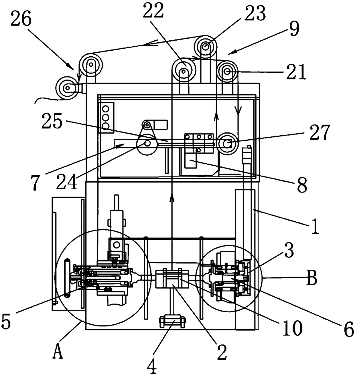
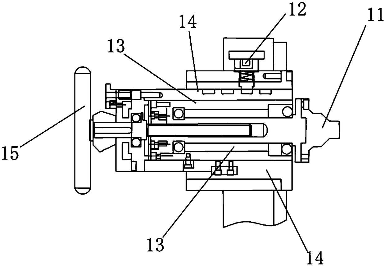
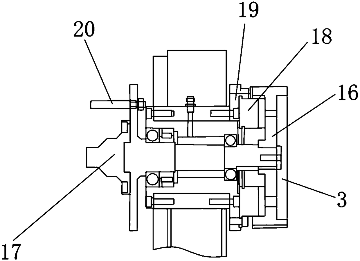
[0024] Such as Figure 1-3 As shown, a wire feeding mechanism provided by the present invention includes a bracket 1, a lifting platform 2, a drive motor 3, a cylinder 4, a movable top cone 5, a fixed top cone 6, a swing arm mechanism 7, a counterweight 8, and a lead guide Wheel set 9, pay-off base 10 and feedback system, the lifting platform 2 is connected with the cylinder 4, the pay-off base 10 is installed on the top of the lifting platform 2, the drive motor 3 is used to drive the release The wire seat 10 rotates, one end of the wire release seat 10 is connected to the movable top cone 5, the other end of the wire release seat 10 is connected to the fixed top cone 6, and the swing arm mechanism 7 is rotatably mounted on On the support 1, one end of the swing arm mechanism 7 is provided with a lead wheel 27, the counterweight 8 is movably mounted on the swing arm mechanism 7, and the lead guide wheel group 9 is installed on the upper end of the support 1 , the feedback sy...

Embodiment 2

[0032] Such as Figure 4As shown, a six-head constant tension wire feeding device with the wire feeding mechanism provided by the present invention includes a wire gathering guide wheel set 26 and six wire feeding mechanisms, and the six wire feeding mechanisms are arranged in a matrix , the wire gathering guide wheel set 26 is arranged at the left end of the wire feeding mechanism, and there are six wire gathering guide wheel sets 26 arranged in sequence. The present invention integrates six wire feeding mechanisms inside a whole machine, and adopts a matrix arrangement, uses the wire gathering guide wheel group 26 to stagger the wire feeding angles of each wire feeding mechanism, and makes full use of the vertical space.


PUM


Abstract

The invention relates to the technical field of wire feeding mechanisms, in particular to a wire feeding mechanism which comprises a support, a lifting table, a drive motor, an air cylinder, a movabletip cone, a fixed tip cone, a swing arm mechanism, a balancing weight block, a wire leading guide wheel group, a despooling seat and a feedback system. According to the wire feeding mechanism provided by the invention, the balancing weight block is adopted for adjusting the despooling tension of the swing arm mechanism, and the feedback system can be used for adjusting the rotating speed of the drive motor, so that a swing arm of the swing arm mechanism and the balancing weight block keep relative balance, so that the despooling tension is constant. The fixed tip cone drives the despooling seat to despoil, the movable tip cone can be used for fixing wire axes with different sizes into the despooling seat, and the despooling seat and the swing arm mechanism are staggered at the up and downposition, so that the vertical space is fully used. The invention provides a six-head type constant-tension wire feeding device with the wire feeding mechanism. Six wire feeding mechanisms are integrated into an overall machine table, and the wire feeding angles of the wire feeding mechanisms are staggered by utilizing wire collecting guide wheel groups, so that the vertical space is fully utilized.

Description

technical field [0001] The invention relates to the technical field of wire feeding devices, in particular to a wire feeding mechanism and a six-head constant tension wire feeding device with the wire feeding mechanism. Background technique [0002] Most of the multi-head pay-off devices used at present adopt multiple independent pay-off racks in the layout of the machine, which are simply placed and fixed on the ground according to the production requirements. The overall structural composition has certain flexibility and low manufacturing cost, but the stability, integrity and operability of the entire cabling system are poor, and it is only suitable for loading smaller sized bobbins, and it is not conducive to the later production line. Reconstruction and reorganization, the overall structure is fragmented and the land area is large. At the same time, the single-spring tension gun and cowhide belt are often used to control the tension of the single pay-off stand, which i...

Claims


Application Information

Patent Timeline
Patent Type & Authority Applications(China)
IPC IPC(8): B65H49/32B65H51/08B65H57/14B65H59/38B65H63/00
CPCB65H49/324B65H51/08B65H57/14B65H59/387B65H63/00B65H2701/34
Inventor 李东兴
Owner 东莞朝隆机械有限公司
Learn More