Nozzle lifting device

A lifting device and nozzle technology, which is applied in the field of sanitation vehicles, can solve problems such as collisions, damage to supports and nozzles, and achieve the effects of reducing collisions, facilitating layout, and reasonable structural design

Active Publication Date: 2018-12-18
ANHUI NANBO ROBOT CO LTD
View PDF9 Cites 0 Cited by
  • Summary
  • Abstract
  • Description
  • Claims
  • Application Information

AI Technical Summary

Problems solved by technology

[0002] The lower part of the current sanitation vehicle is mostly provided with nozzles on the support, and the support can be lifted. When the nozzle is not working, the nozzle on the support rises, and when it is

Method used


Image

  • Nozzle lifting device
  • Nozzle lifting device
  • Nozzle lifting device

Examples


Embodiment Construction

[0022] The specific implementation manner of the present invention will be described in further detail below by describing the embodiments with reference to the accompanying drawings.

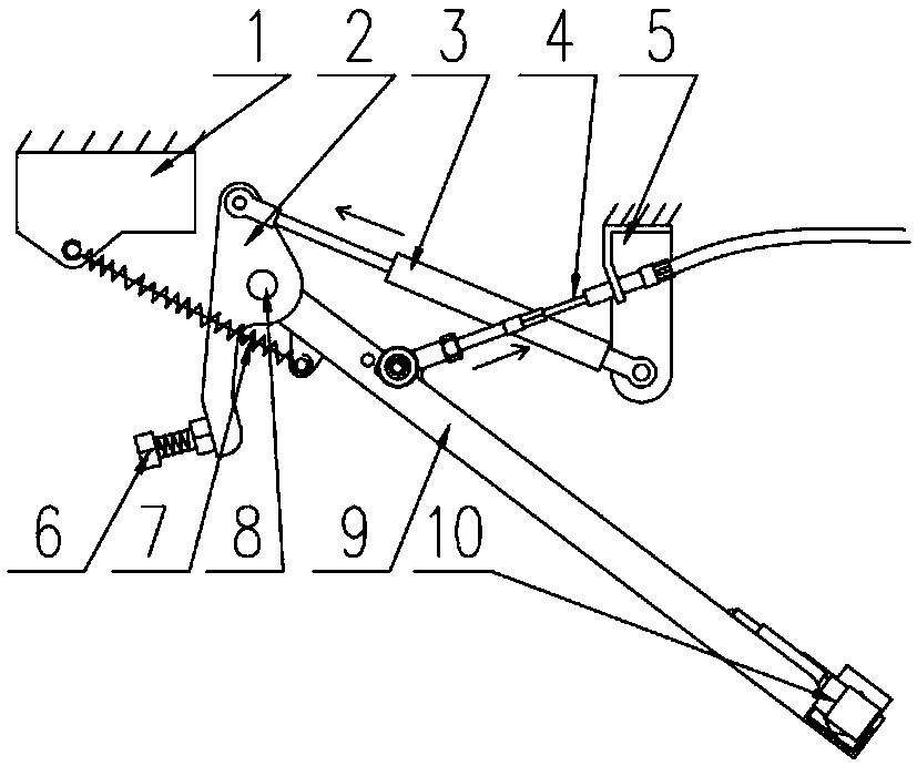
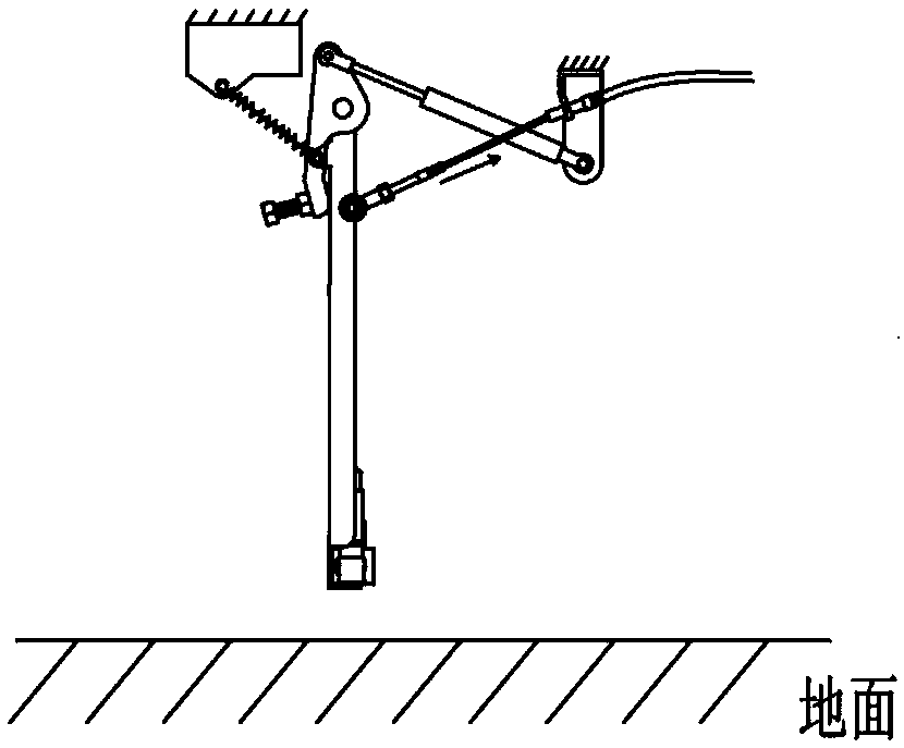
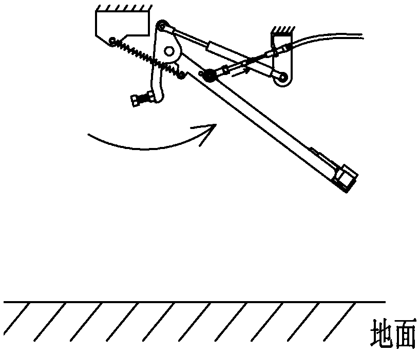
[0023] Such as Figure 1 to Figure 5 As shown, the nozzle lifting device includes a base, a lifting arm 9 , an anti-collision rotary block 2 , a sheath stay wire 4 and a nozzle 10 located at the lower end of the lifting arm 9 .

[0024] The upper end of the lifting arm 9 and the anti-collision turning block 2 are hinged on the base through the rotating shaft 8, the lower end of the anti-collision turning block 2 is aligned with the lifting arm 9 front and rear, and nitrogen gas is provided between the upper end of the anti-collision turning block 2 and the base II5 The spring 3 is provided with a tension spring 7 between the upper part of the lifting arm and the base I1.

[0025] Base Ⅰ1 and base Ⅱ5 are respectively located on both sides of the lifting arm, and both bases are located on the ch...


PUM


Abstract

The invention discloses a nozzle lifting device which includs a base, a lifting arm and a nozzle provided at the lower end of the lifting arm, The upper end of the lifting arm is hinged on the base through a rotating shaft, and further comprises an anti-collision rotating block, wherein the anti-collision rotating block is hinged on the base, the lower end of the anti-collision rotating block isaligned with the front and rear of the lifting arm, a nitrogen spring is arranged between the upper end of the anti-collision rotating block and the base, and a tension spring is arranged between theupper part of the lifting arm and the base. As that forward travel nozzle of the vehicle meets an obstacle, the lifting arm and the nozzle rotate backward clockwise to avoid collision, and when the backward traveling nozzle of the vehicle meets an obstacle, the lifting arm and the nozzle rotate forward counterclockwise to avoid collision, so that the impact of the obstacle on the nozzle can be effectively reduced, and stable and reliable work under various complex conditions is ensured; And is compact in structure and easy to arrange.

Description

technical field [0001] The invention relates to the technical field of sanitation vehicles, in particular to a nozzle lifting device. Background technique [0002] The lower part of the current sanitation vehicle is mostly provided with nozzles on the support, and the support can be lifted. When the nozzle is not working, the nozzle on the support rises, and when it is working, the nozzle on the support is lowered. The nozzle on the support is closer to the ground; , The nozzle is easy to collide with obstacles on the road, and it is easy to cause damage to the bracket and the nozzle. Contents of the invention [0003] Aiming at the deficiencies of the prior art, the technical problem to be solved by the present invention is to provide a nozzle lifting device to achieve the purpose of effectively reducing the impact of obstacles on the nozzle. [0004] In order to solve the problems of the technologies described above, the technical solution adopted in the present inventi...

Claims


Application Information

Patent Timeline
IPC IPC(8): E01H1/00E01H1/10
CPCE01H1/00E01H1/10
Inventor 陈利刘兵胡俊方宇石照刚陈宏
Owner ANHUI NANBO ROBOT CO LTD
Why Eureka
Try Eureka