A safety monitoring system for gas use
A safety monitoring system and gas technology, applied in the direction of safety valves, pipeline systems, valve operation/release devices, etc., can solve problems such as leakage alarms, and achieve the effects of ensuring safe use, improving user experience, and ensuring family safety
- Summary
- Abstract
- Description
- Claims
- Application Information
AI Technical Summary
Problems solved by technology
Method used
Image

Examples
Embodiment 1
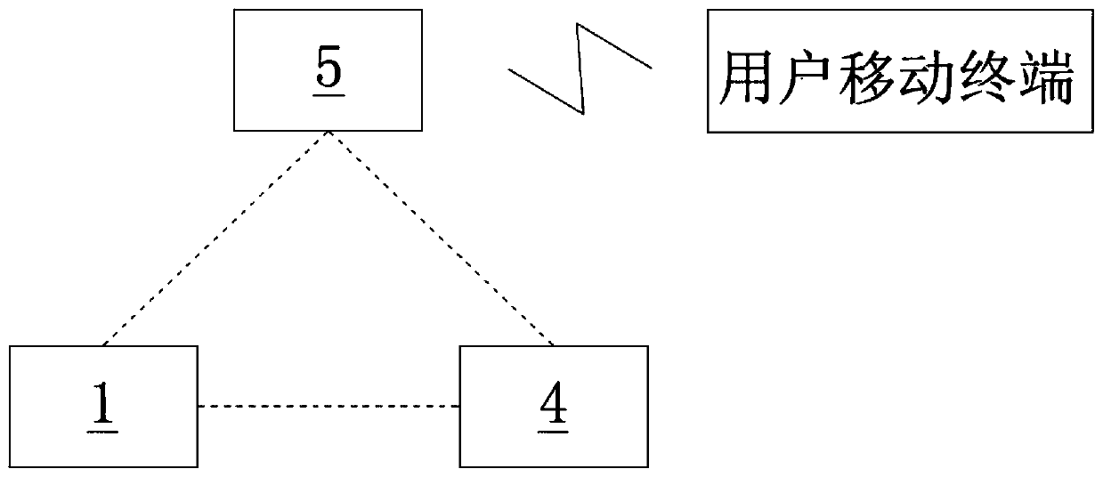
[0055] Such as figure 1 As shown, a gas safety monitoring system according to the present invention includes a pressure detection valve 1 , an entry valve 4 and a background management center 5 . The entry valve 4 is arranged on the entry pipe of the gas pipeline to control the on-off of the entry pipe and the supply of gas. One end of the pressure detection valve 1 is connected to the indoor pipeline of the gas pipeline, and the other end is connected to the household pipeline. The pressure detection valve 1 is used to detect the abnormality of the air supply pressure of the indoor pipeline, and then judge whether leakage or abnormal air supply occurs. The pressure detection valve 1 is wirelessly connected with the entry valve 4 . The background management center 5 interacts with the pressure detection valve 1 and the entry valve 4 respectively based on wireless network communication.
[0056] Wherein, the pressure detection valve 1 is provided with a mechanical automatic ...
Embodiment 2
[0071] The safety monitoring system for gas use described in Embodiment 2 is similar in structure and principle to Embodiment 1. Specifically, the structure of the pressure detection valve is described in detail:
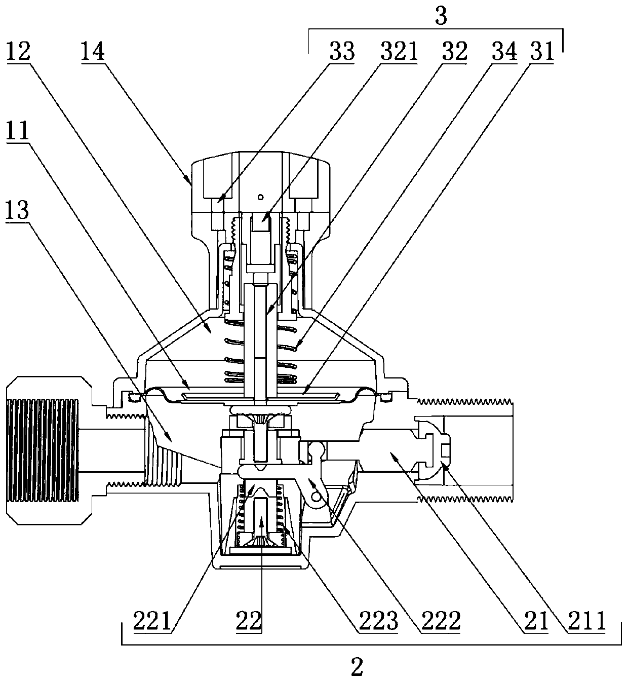
[0072] Such as figure 2 As shown, specifically, the pressure detection valve 1 includes a valve body, a diaphragm 11 , a first pressure balance mechanism 3 and a second pressure balance mechanism 2 . The diaphragm 11, the first pressure balance mechanism 3 and the second pressure balance mechanism 2 jointly constitute a mechanical automatic closing device.
[0073] Wherein, the diaphragm 11 divides the chamber of the valve body into an upper chamber 12 and a lower chamber 13 that are not connected to each other; the lower chamber 13 is provided with two gas ports; the first pressure balance mechanism 3 Placed in the upper chamber 12 and connected with the diaphragm 11; the second pressure balance mechanism 2 is straddled between the lower chamber 13 and a gas inte...
Embodiment 3
[0096] The safety monitoring system for the use of gas described in Embodiment 3 is similar in structure and principle to Embodiment 1. Specifically, the entry pipeline 4 is described, and the entry valve 4 is a pipeline solenoid valve. The structure is as follows:
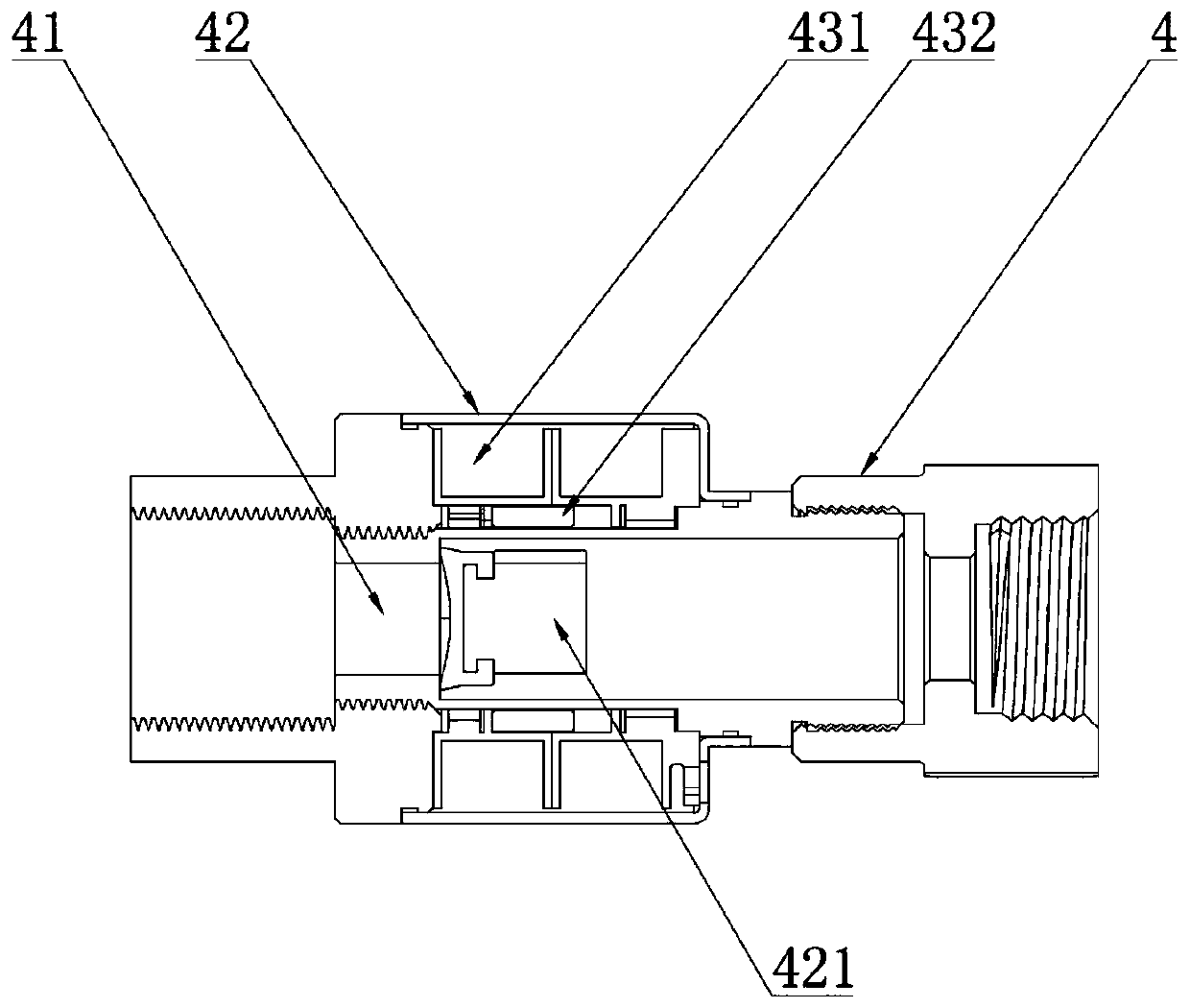
[0097] The entry valve 4 is the pipeline electromagnetic valve 4 , which includes a hollow pipe body 41 , a sealing assembly 42 and an electromagnetic driving assembly 43 .
[0098] Such as image 3 As shown, specifically, the inner wall of the hollow tube body 41 has a stepped structure, so that the inside of the hollow tube body 41 has a first cavity and a second cavity parallel to each other. Both the first cavity and the second cavity are cylindrical cavities, and the diameter of the first cavity is larger than that of the second cavity; the boundary plane between the two is the stepped platform of the stepped structure, which is an annular .
[0099] In this embodiment, preferably, the stepped platform is ...
PUM
 Abstract
Description
Claims
Application Information
 - R&D
- Intellectual Property
- Life Sciences
- Materials
- Tech Scout
- Unparalleled Data Quality
- Higher Quality Content
- 60% Fewer Hallucinations
Browse by: Latest US Patents, China's latest patents, Technical Efficacy Thesaurus, Application Domain, Technology Topic, Popular Technical Reports.
© 2025 PatSnap. All rights reserved.Legal|Privacy policy|Modern Slavery Act Transparency Statement|Sitemap|About US| Contact US: help@patsnap.com