Diode and triode testing circuit, circuit board and detector

A diode and triode technology, used in the field of test circuits, can solve problems such as component failure, obsolescence, and inability to produce results from experiments

Pending Publication Date: 2018-12-18
ANQING NORMAL UNIV
View PDF5 Cites 2 Cited by
  • Summary
  • Abstract
  • Description
  • Claims
  • Application Information

AI Technical Summary

Problems solved by technology

In addition, in the teaching experiments of colleges and universities, such as analog electronic technology experiments, digital electronic technology experiments, electronic engineering experiments, etc., large-scale use of experimental boxes is required, and students often cause some elements to be damaged due to improper operation or lack of rigor. Component failures lead to the failure of experiment results and affect the teaching effect. Among them, diodes and triodes are the components with the highest failure frequency. At this time, an instrument that can quickly detect failures is especially needed
[0003] At present, with the advancement of electronic technology, some methods are outdated and useless

Method used


Image

  • Diode and triode testing circuit, circuit board and detector
  • Diode and triode testing circuit, circuit board and detector
  • Diode and triode testing circuit, circuit board and detector

Examples


Embodiment 1

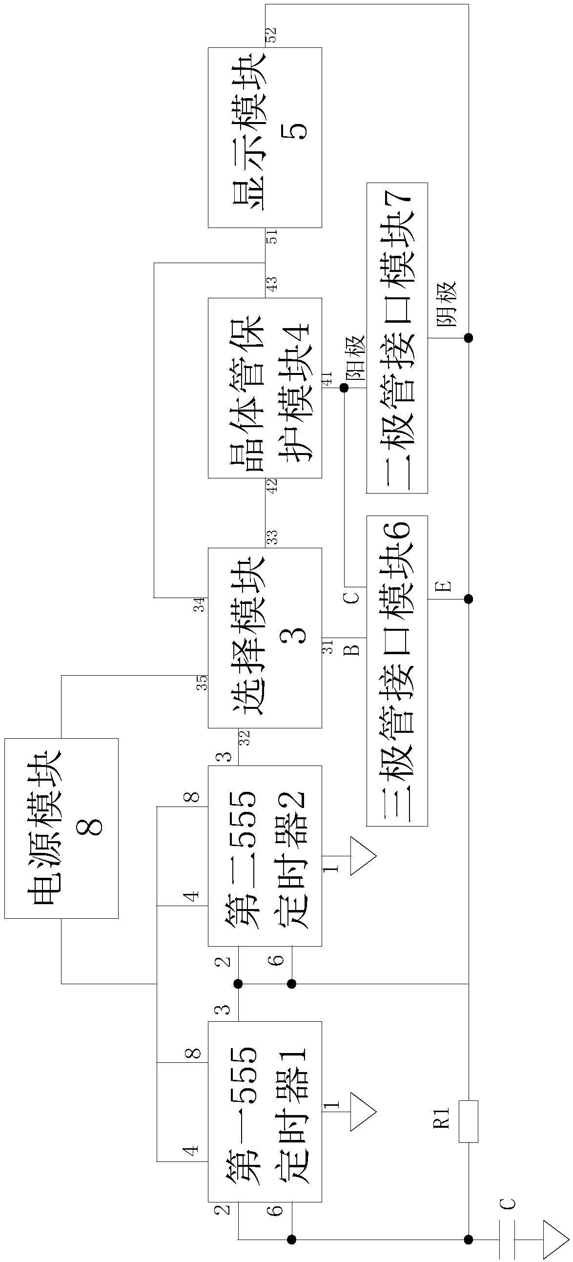
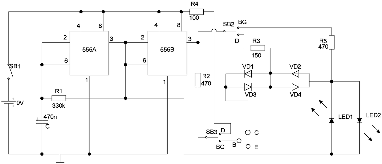
[0037] Such as figure 1 As shown, a circuit for testing diodes and triodes includes a power supply module 8, a selection module 3, a transistor protection module 4, and the first 555 timer 1 (in figure 2 555A in), the second 555 timer 2 (in figure 2 555B in the middle), display module 5, triode interface module 6 and diode interface module 7. The fourth pin and the eighth pin of the first 555 timer 1 and the second 555 timer 2 are connected to the power module 8, and the second pin and the sixth pin of the first 555 timer 1 are connected and divided into two One way, one way is connected to the second pin and the sixth pin of the second 555 timer 2 through the resistor R1, and the other way is connected to the ground through the capacitor C, the third pin of the first 555 timer 1 and the second 555 timing The second pin and the sixth pin of the device 2 are connected as the cathode of the diode interface module 7 and the emitter of the triode interface module 6; the outpu...

Embodiment 2

[0054] A circuit board including the circuit in embodiment 1 is that the circuit in embodiment 1 is solidified on the circuit board by wiring welding.

Embodiment 3

[0056] Such as Figure 4 As shown, a detector comprising the circuit board of Embodiment 2 also includes a housing 9, a first plug-in terminal with two jacks, and a second plug-in terminal with three jacks, on the housing 9 Set the slot 10 through which the first plug-in terminal and the second plug-in terminal pass, install the installation holes 11 for the display lights LED1 and LED2, the circuit board is arranged in the housing 9, the first socket and the second socket The terminals are correspondingly connected to the pins on the corresponding diode interface module 7 and triode interface module 6 respectively, and the other ends of the first socket and the second socket are used to insert corresponding diodes and triodes to be detected.


PUM


Abstract

The invention discloses a diode and triode testing circuit, a circuit board and a detector. The circuit comprises a power module, a selection module, a transistor protection module, a first 555 timer,a second 555 timer, a display module, a triode interface module and a diode interface module, wherein the fourth pin and the eighth pin of the first 555 timer and the fourth pin and the eighth pin ofthe second 555 timer are all connected with the power module; the second pin and the sixth pin of the first 555 timer are connected and then divided into two paths, wherein one path is connected withthe second pin and the sixth pin of the second 555 timer through a resistor R1, and the other path is connected with the ground through a capacitor C; the third pin of the first 555 timer and the second pin of the second 555 timer are connected to serve as a cathode of the diode interface module, and the third pin of the first 555 timer and the sixth pin of the second 555 timer are connected to serve as an emitter of the triode interface module; and the output end of the second 555 timer is connected with the selection module. The circuit has the advantage that it is convenient to test various states of diodes and triodes.

Description

technical field [0001] The invention relates to the field of testing circuits, in particular to a circuit, a circuit board and a detector for testing diodes and triodes. Background technique [0002] With the continuous development of modern information technology in our country, electronic products occupy an important position and role in people's daily life, among which semiconductor devices are an important part of electronic equipment. In the process of continuous development of electronic equipment, semiconductor components play an important role and significance, and play a decisive role in the normal operation of the entire electronic product. However, during the operation of electronic components, some basic components, such as diodes and triodes, often have various problems, which seriously or even hinder the progress of experiments and the development of electronic technology. Therefore, under such circumstances, the detection of semiconductor components is very i...

Claims


Application Information

Patent Timeline
Patent Type & Authority Applications(China)
IPC IPC(8): G01R31/26
CPCG01R31/2607G01R31/2632
Inventor 王鹏裴悦王钰涵徐晓峰占生宝王陈宁查长礼郭玉
Owner ANQING NORMAL UNIV
Why Eureka
Try Eureka