Antitheft type light-operated circuit

A light-controlled circuit and anti-theft technology, applied in the field of alarm, can solve the problems of poor sensitivity, complex alarm circuit, poor anti-theft effect, etc., and achieve the effect of low cost, good anti-theft effect and stable work

Inactive Publication Date: 2015-05-06
CHENGDU HONGSHAN TECH
View PDF2 Cites 1 Cited by
  • Summary
  • Abstract
  • Description
  • Claims
  • Application Information

AI Technical Summary

Problems solved by technology

Today's alarm circuits have defects such as complex circuits, poor sensitivity, and poor anti-theft effects.

Method used


Image

  • Antitheft type light-operated circuit

Examples


Embodiment 1

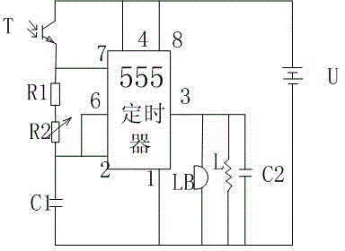
[0016] Such as figure 1 As shown, the present invention includes a 555 timer, a phototransistor T, a buzzer LB, an inductor L and a 6V power supply U, the port 4 of the 555 timer is connected to the port 8, and the port 4 of the 555 timer is also connected to the phototransistor T The collector of the phototransistor T and the emitter of the phototransistor T are connected to the port 7 of the 555 timer and the resistor R1 at the same time, and the port 2 and port 6 of the 555 timer are connected to the sliding rheostat R2 at the same time, and the other end of the sliding rheostat R2 is connected to the resistor R1. The 555 timer Connect capacitor C1 between port 1 and port 2, connect buzzer LB between port 1 and port 3 of 555 timer, connect 6V power supply between port 1 and port 8 of 555 timer.

[0017] The working principle of the circuit is as follows: When installing, first place the part of the circuit with the phototransistor T in a dark place such as a drawer or a bo...

Embodiment 2

[0019] This embodiment is preferably as follows on the basis of Embodiment 1: both ends of the buzzer LB are connected in parallel with an inductor L and a capacitor C2. Parallel capacitors and inductors prevent sudden changes in the voltage and current at both ends of the buzzer, absorb surge voltage and current, and protect the buzzer.

[0020] The model of the phototransistor T is 3DU5. This type of phototransistor has high sensitivity, high cost performance and low cost.

[0021] The model of the 555 timer is NE555DR.


PUM


Abstract

The invention discloses an antitheft type light-operated circuit. The antitheft type light-operated circuit comprises a 555 timer, a phototriode T, a buzzer LB, an inductor L and a 6V power source U. A port 4 and a port 8 of the 555 timer are connected, the port 4 of the 555 timer is also connected with a collector of the phototriode T, an emitter of the phototriode T is connected with a port 7 of the 555 timer and a resistor R1, a port 2 and a port 6 of the 555 timer are connected with a slide rheostat R2, and the other end of the slide rheostat R2 is connected with the resistor R1. A capacitor C1 is connected between a port 1 and the port 2 of the 555 timer, the buzzer LB is connected between the port 1 and a port 3 of the 555 timer, and the 6V power source is connected between the port 1 and the port 8 of the 555 timer. The antitheft type light-operated circuit has the advantages of simplicity, low cost, high flexibility and good antitheft effect.

Description

technical field [0001] The invention relates to the field of alarm, in particular to an anti-theft light control circuit. Background technique [0002] With the progress of the times, the development of the national economy, and the rapid development of electronic circuit science and technology, people's living standards have been greatly improved. Various high-end home appliances and valuables are owned by many families. However, some lawbreakers are becoming more and more many. However, most people's anti-theft awareness is still not strong enough to cause the phenomenon of theft, which brings great troubles to the people. Therefore, more and more residents are very worried about property safety. Nowadays, due to the needs of social security assurance and electronic security assurance, the comprehensive technology of electronic alarm is constantly developing. Some important departments such as unguarded family, bank, warehouse, store, important finance and economics depa...

Claims


Application Information

Patent Timeline
Patent Type & Authority Applications(China)
IPC IPC(8): G08B13/189
CPCG08B13/1895
Inventor 黄友华
Owner CHENGDU HONGSHAN TECH
Why Eureka
Try Eureka