Motor running timing control circuit based on chips

A timing control circuit and chip technology, which is applied in the direction of AC motor direction control, control/regulation system, and electric variable adjustment to achieve the effect of simple circuit structure.

Inactive Publication Date: 2018-02-23
张昕
View PDF4 Cites 2 Cited by
  • Summary
  • Abstract
  • Description
  • Claims
  • Application Information

AI Technical Summary

Problems solved by technology

At present, the commonly used method is to switch the motor windings to any two of the three power phase wires. The direction of the rotating magnetic field will be opposite to the original direction, and the direction of the rotor driven by it will also be reversed. In this way, the positive and negative rotation of the motor can be realized. The switch converts the contacts, but this method requires a special person to do it manually, and the person must control the time

Method used


Image

  • Motor running timing control circuit based on chips

Examples


Embodiment Construction

[0015] Below in conjunction with accompanying drawing, the chip-based motor running timing control circuit of the present invention is further described:

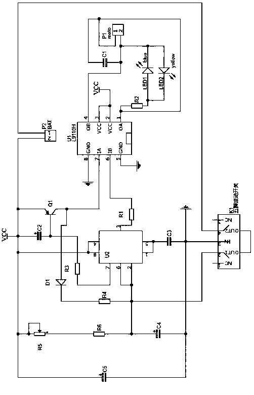
[0016] Such as figure 1 As shown, a chip-based motor operation timing control circuit includes a five-pin toggle switch, a timing control circuit and a drive circuit;

[0017] The timing control circuit includes a timer U2, capacitors C2, C3, C4, C5, resistors R1, R3, R5, sliding resistor R5, the pin 1 and pin 5 of the timer U2 are connected to the five-pin dial through the capacitor C3 The IN pin of the dynamic switch is connected, the pin 1 and the pin 5 are grounded at the same time, the sliding resistor R5, the resistor R6 and the capacitor C4 are connected in series between the positive and negative poles of the power supply, and the capacitor C5 is connected in parallel to the sliding resistor R5 and the capacitor At both ends of C4, the pin 2 and pin 6 of the timer U2 are connected between the resistor R5 and the ca...


PUM


Abstract

The invention relates to a motor running timing control circuit based on chips. The circuit comprises a five-pin toggle switch, a timing control circuit and a driving circuit, wherein the timing control circuit comprises a timer U2, capacitors C2, C3, C4 and C5, resistors R1, R3 and R5 and a slide resistor R5; the driving circuit comprises a chip U1, a triode Q1 and a diode D1. According to the motor running timing control circuit based on the chips, the timing control chip is a 555 timer, a control circuit in the motor current direction is formed by use of voltage change of pins 3 and 7 of the 555 timer, a motor driving chip is L9110S, has an H-bridge circuit inside and can drive a motor to rotate through larger current. Besides, by use of the reverse interception feature of the diode D1,a direction indicator lamp is rotated through the motor, and forward and reverse rotation of the motor can be observed directly.

Description

technical field [0001] The invention relates to the field of circuit control, in particular to a chip-based motor operation timing control circuit. Background technique [0002] In real life, some production machinery needs to rotate in two directions, so the motor is required to have the function of forward and reverse. At present, the commonly used method is to switch the motor windings to any two of the three power phase wires. The direction of the rotating magnetic field will be opposite to the original direction, and the direction of the rotor driven by it will also be reversed. In this way, the positive and negative rotation of the motor can be realized. The switch converts the contacts, but this method requires a special person to do it manually, and the person must control the time. Contents of the invention [0003] The object of the present invention is to provide a motor running timing control circuit based on a chip, which uses a timing control chip to control...

Claims


Application Information

Patent Timeline
Patent Type & Authority Applications(China)
IPC IPC(8): H02P23/24G05F1/56
CPCG05F1/561H02P23/24
Inventor 张昕
Owner 张昕
Why Eureka
Try Eureka