Energy-saving boost relay

A technology of high-voltage relays and relays, applied to relays, circuits, electrical components, etc., can solve the problems of high rated power, high total energy consumption, and low total energy consumption of relays, so as to improve the reliability of use, service life, and total power consumption. The effect of low energy consumption and small total energy consumption

Pending Publication Date: 2018-12-18
ZHEJIANG YINGLUOHUA NEW ENERGY TECH CO LTD
View PDF10 Cites 4 Cited by
  • Summary
  • Abstract
  • Description
  • Claims
  • Application Information

AI Technical Summary

Problems solved by technology

[0003] The present invention provides a method to effectively monitor the on-off information status of the high-voltage contacts of the high-voltage relay in order to solve the current situation of the existing high-voltage relays, such as high relay rated power and high total energy consumption, and improve the reliability of the high-voltage relay. and service life, use the relay to maintain the operation of the pull-in power, reduce the waste of power, and the energy-saving booster relay with low total energy consumption

Method used


Image

  • Energy-saving boost relay
  • Energy-saving boost relay

Examples


Embodiment Construction

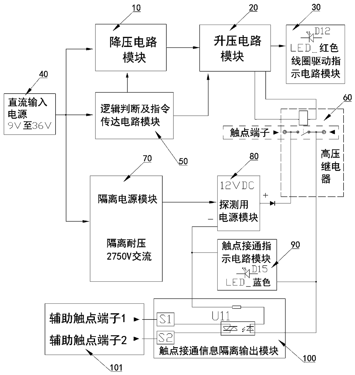
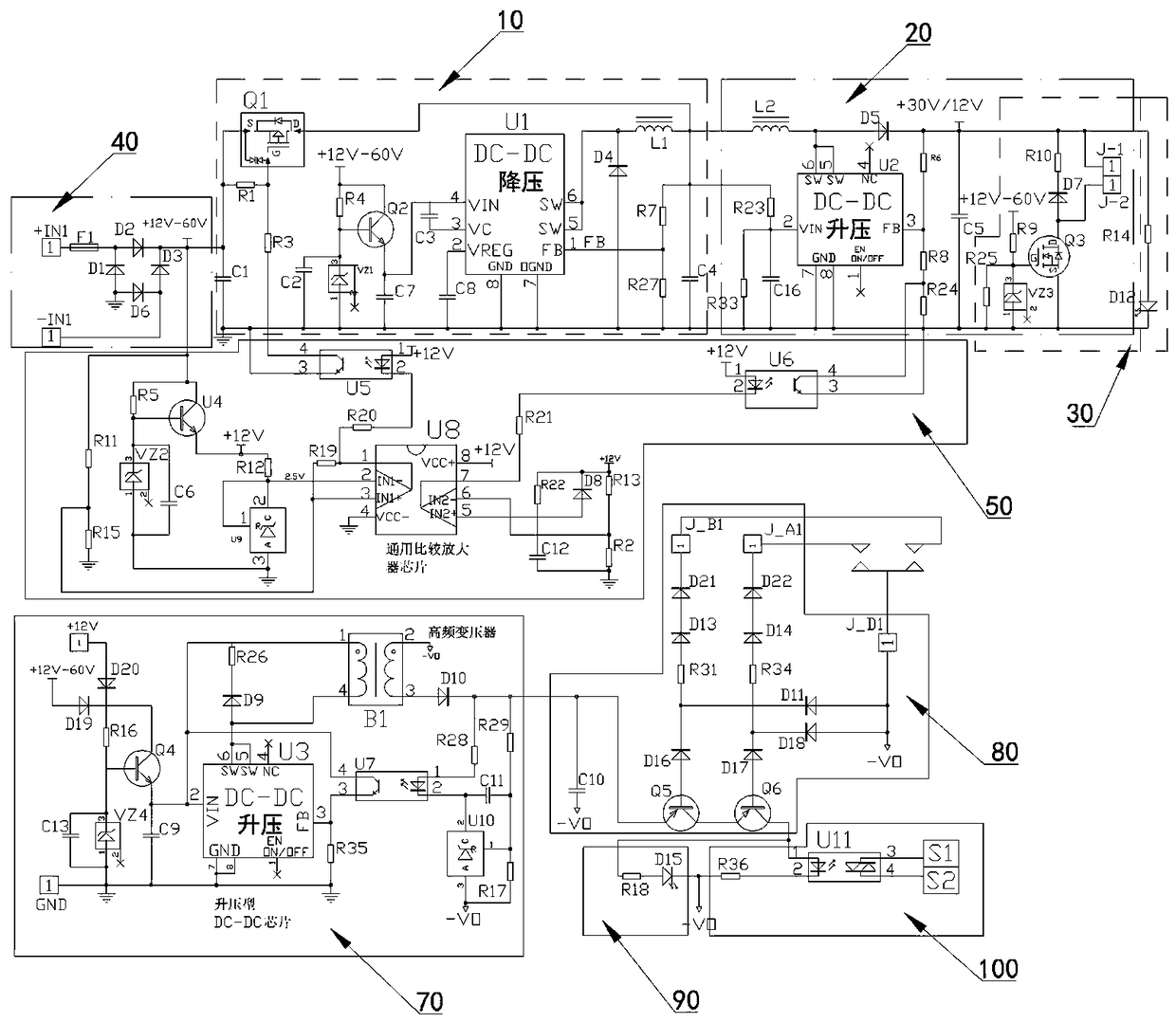
[0015] figure 1 , figure 2In the shown embodiment, an energy-saving booster relay includes a DC input power supply 40, a high-voltage relay 60 contacts and a coil, and also includes an isolated power supply module 70, a step-down circuit module 10, a booster circuit module 20, logic judgment and Instruction transmission circuit module 50 and the coil drive indicating circuit module 30 provided with relay coil drive indicator light; the front stage of the isolated power supply module 70 is electrically connected to the DC input power supply 40, and the two terminals J-1 / J-2 connected to the relay coil are connected to The coil driving indicating circuit module of the relay coil driving indicator light is electrically connected to each other. It is electrically connected with the step-down circuit module and the logic judgment and instruction transmission circuit module. The front stage of the step-down circuit module is electrically connected with the DC input power supply an...


PUM


Abstract

The invention discloses an energy-saving booster relay, A front stage of the isolated power module is electrically connected to a DC input power supply. A step-up circuit module is arrange in front ofthat coil driving indication circuit module, A low stage of that boost circuit module is electrically connected to the high voltage relay coil, A step-up circuit module front stage is electrically connected with a step-down circuit module and a logic judgment and instruction transmission circuit module respectively, A step-down circuit module is electrically connected with a DC input power supplyand a logic judgment and instruction transmission circuit module respectively, and when that logic judgment and instruction transmission circuit module judge to obtain a high-voltage relay on signal,the step-up circuit module is conveyed to control the boosting instantaneous voltage; A step-down circuit module, a step-up circuit module, a logic judgment and instruction transmission circuit module, and a coil driving instruction circuit module are integrate into that relay to form an integral relay structure, and the step-down circuit module, the step-up circuit module, the logic judgment andinstruction transmission circuit module, and the coil driving instruction circuit module are integrated into the relay. The utility model improves the service reliability and service life of the high-voltage relay, reduces energy consumption and waste, and has low total energy consumption.

Description

technical field [0001] The invention relates to a relay, in particular to an energy-saving booster relay capable of detecting the on-off information status of a high-voltage contact of the high-voltage relay. Background technique [0002] Usually, high-voltage relays are used in equipment that requires random monitoring and remote monitoring, such as electric vehicles and charging piles. The power of the driving coil of the high-voltage relays currently used in these devices is usually designed to meet the pull-in time of the relay. On the power demand index, and most of the time, the relay works in the period of maintaining pull-in. The power requirement for maintaining the pull-in period is usually less than 0.4 times the power requirement for the pull-in period. However, the existing high-voltage relays are always running according to the power design requirements of the pull-in time period, resulting in waste of power, high total energy consumption, and it is not conduc...

Claims


Application Information

Patent Timeline
Patent Type & Authority Applications(China)
IPC IPC(8): H01H47/00H01H47/02H01H47/32
CPCH01H47/002H01H47/02H01H47/325
Inventor 陈永辉陈永其许剑雷杜德进陈璇
Owner ZHEJIANG YINGLUOHUA NEW ENERGY TECH CO LTD
Why Eureka
Try Eureka