Corrugated pipe forming machine
A forming machine and corrugated pipe technology, applied in the field of pipe processing equipment, can solve the problems of high time cost, difficulty in determining the pitch, high equipment cost, etc.
- Summary
- Abstract
- Description
- Claims
- Application Information
AI Technical Summary
Problems solved by technology
Method used
Image

Examples
Embodiment 1
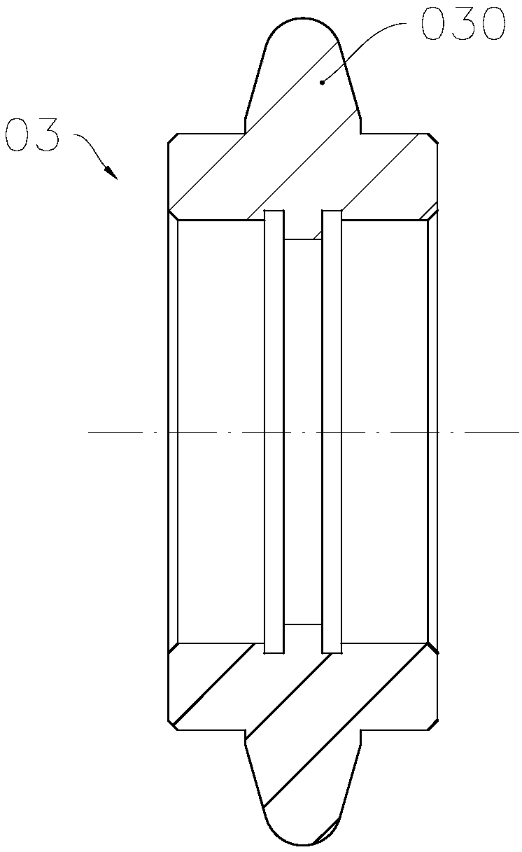
[0049] see Figure 5 to Figure 20 , The bellows forming machine 1 of the present invention includes a frame 10 , a control unit, a feeding trolley 2 and a forming head 3 installed on the frame 10 . The frame 10 includes a protective cover 100 covering the forming machine head 3, and the two ends of the protective cover 100 are open ends for the tube blank 05 to pass through during the forming process. The control unit includes a processor, a memory and a touch control screen 11. The processor receives input instructions from the operator through the touch control screen 11, and at the same time controls the forming head 3 and the feeding trolley 2 in a predetermined order by executing the computer program stored in the memory. action to execute the bellows forming process.
[0050] Such as Figure 5 and Image 6 As shown, the feeding trolley 2 includes an axial feed drive unit and a clamping die 24 installed on the mover of the axial feed unit. The axial feed drive unit in...
Embodiment 2
[0074] As a description of Embodiment 2 of the corrugated tube forming machine of the present invention, only differences from the above-mentioned Embodiment 1 of the corrugated tube forming machine will be described below.
[0075] In this embodiment, the molding machine in Embodiment 1 is used to form such Figure 4 The bellows structure shown is the bellows in which the cross-section of the tube substrate is formed into an ellipse.
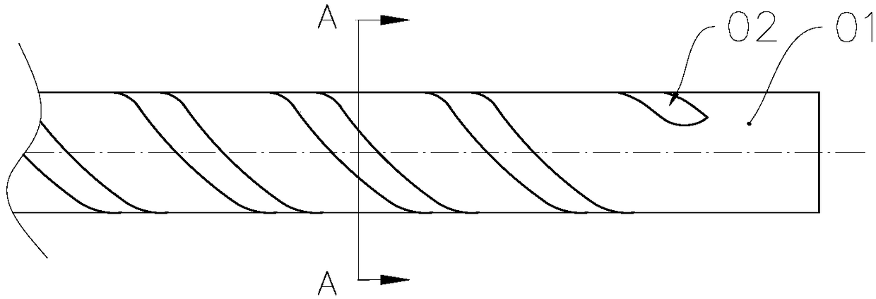
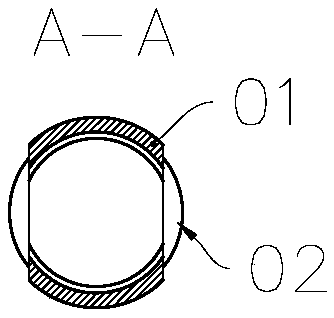
[0076] see Figure 21 and Figure 22 , using this bellows forming machine to form a spiral groove on the tube blank 06 with an elliptical cross section to obtain a non-circular bellows. The cross section of the tube blank 06 used is a circular structure. Wherein, the outer diameters of the arc-shaped parts 61 and 65 on the extrusion roller 6 are larger than the outer diameter of the tube blank 06 and equal to the length of the major axis of the formed corrugated tube base 07 .
[0077] During the forming process, as the extrusion driving dev...
Embodiment 3
[0080] As a description of Embodiment 3 of the corrugated tube forming machine of the present invention, only the differences from the above-mentioned Embodiment 1 of the corrugated tube forming machine will be described below.
[0081] see Figure 23 , 3 sets of extrusion rollers 6 uniformly arranged axially around the main shaft are installed on the rotating drive main shaft to form a three-headed helical groove structure on the tube blank 07, that is, the groove depth of the helical groove and the extrusion If the axial dimension of the roller 6 allows, the number of extrusion rollers can be increased to obtain multi-head bellows structures such as 3 heads, 4 heads, and 5 heads.
PUM
 Abstract
Description
Claims
Application Information
 - R&D
- Intellectual Property
- Life Sciences
- Materials
- Tech Scout
- Unparalleled Data Quality
- Higher Quality Content
- 60% Fewer Hallucinations
Browse by: Latest US Patents, China's latest patents, Technical Efficacy Thesaurus, Application Domain, Technology Topic, Popular Technical Reports.
© 2025 PatSnap. All rights reserved.Legal|Privacy policy|Modern Slavery Act Transparency Statement|Sitemap|About US| Contact US: help@patsnap.com