Pin shaft assembly equipment

A technology for assembling equipment and pins, which is applied to metal processing equipment, metal processing, manufacturing tools, etc., can solve problems such as safety accidents and low work efficiency, and achieve the effect of preventing skew

Pending Publication Date: 2018-12-21
WUHAN LIANHANG ELECTROMECHANICAL
View PDF0 Cites 4 Cited by
  • Summary
  • Abstract
  • Description
  • Claims
  • Application Information

AI Technical Summary

Problems solved by technology

This method has low work efficiency, and the manual press-fit method requires workers to hold the pin shaft during

Method used


Image

  • Pin shaft assembly equipment
  • Pin shaft assembly equipment
  • Pin shaft assembly equipment

Examples


Embodiment Construction

[0077] The technical solutions of the present invention will be further described below in conjunction with the accompanying drawings and through specific implementation methods.

[0078] Before the spindle-shaped workpiece is assembled with the formal pin shaft, it is necessary to fix the position of the four gears. In the actual assembly process, the assembly shaft and the four gears are used as the support of the four gears. The assembly shaft and the formally installed pin shaft The structure is similar, and then the pin shaft is used instead of the assembly shaft to complete the assembly of the spindle-shaped workpiece.

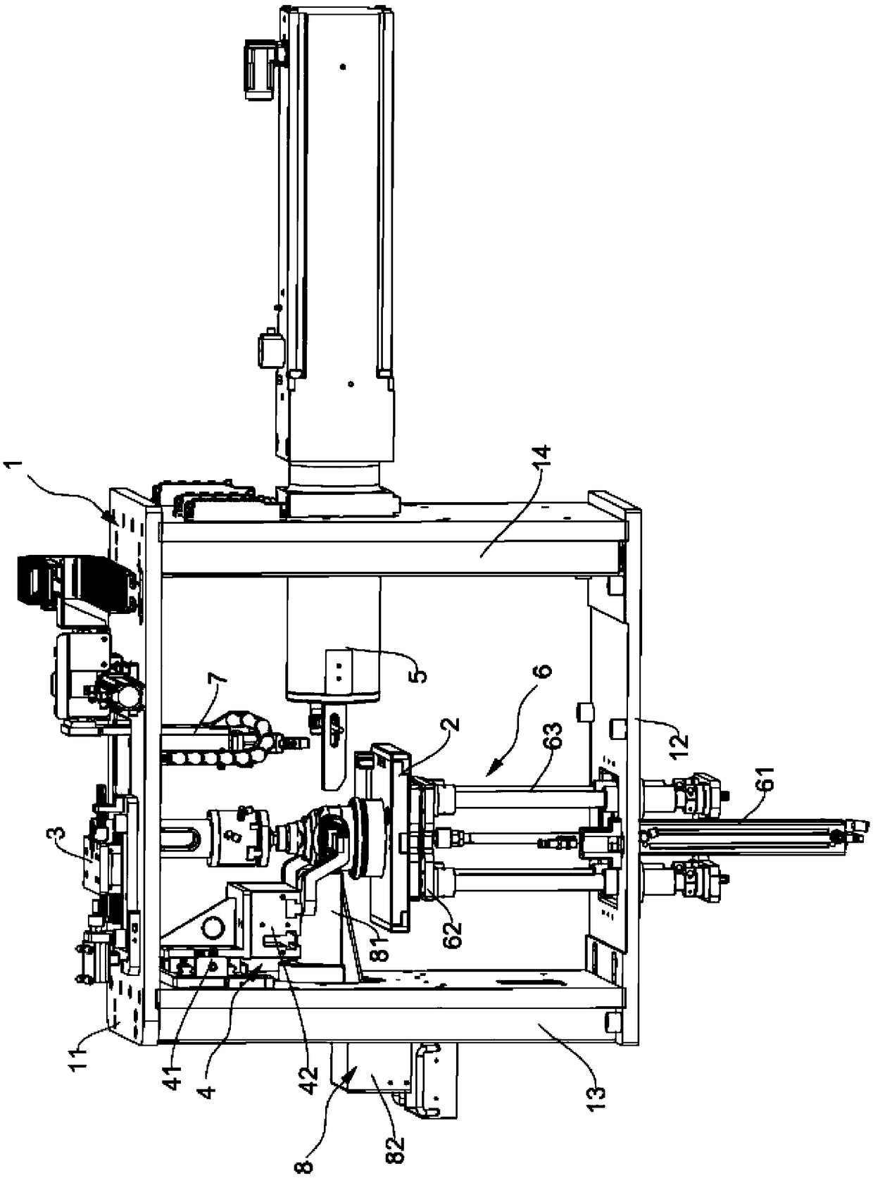
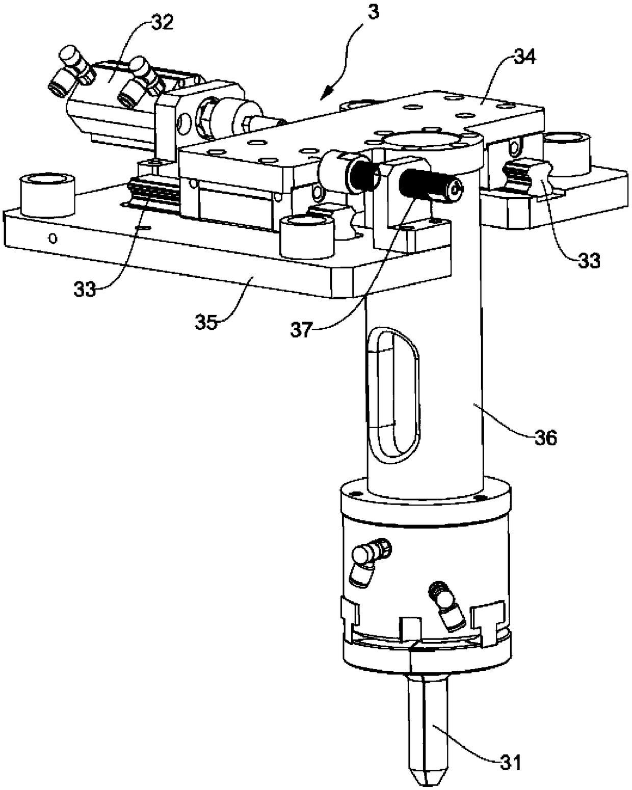
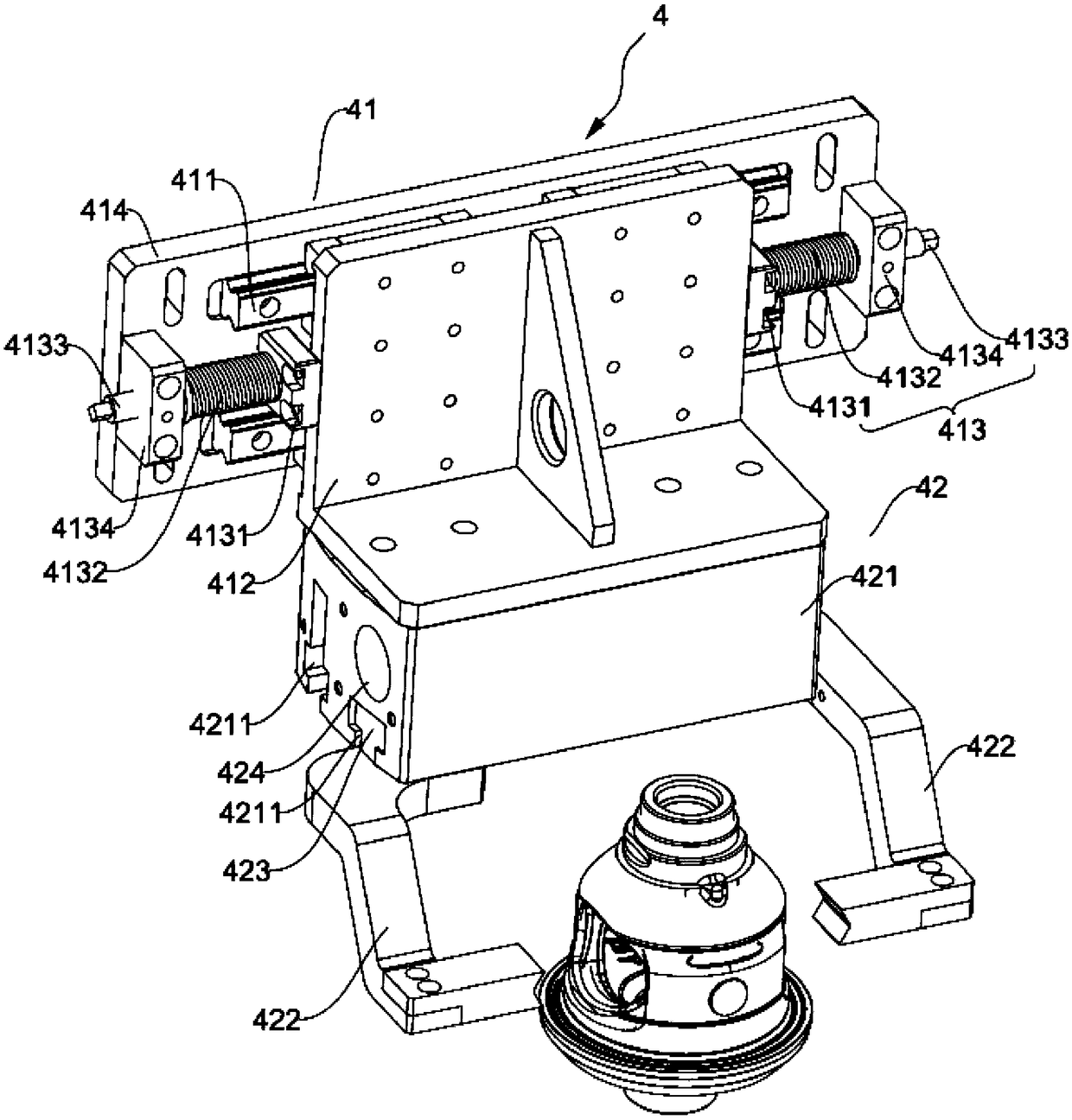
[0079] Such as figure 1 As shown, specifically, the above-mentioned pin assembly equipment includes a fixed bracket 1 , a lifting assembly 6 , a pin feeding assembly 7 , an X-direction positioning assembly 3 , a Y-direction floating clamping assembly 4 , a workbench 2 , and a pressing assembly 5 . Wherein, the fixed bracket 1 is composed of four support...


PUM


Abstract

The invention relates to the technical field of automobiles and discloses pin shaft assembly equipment. The pin shaft assembly equipment comprises a fixed bracket, a workbench, an X-direction positioning assembly, a Y-direction floating clamping assembly, a press-fitting assembly and a lifting assembly. The workbench is arranged on the fixed bracket and is used for containing workpieces to be assembled. The X-direction positioning assembly and the Y-direction floating clamping assembly are both arranged on the fixed bracket, and the X-direction positioning assembly comprises a clamping piece which can move in the X direction relative to the fixed bracket. After the clamping piece and the Y-direction floating clamping assembly clamp the workpieces, the Y-direction floating clamping assemblycan move in the Y direction relative to the fixed bracket. The press-fitting assembly is arranged on the fixed bracket and presses pin shafts into the workpieces. The lifting assembly is arranged onthe fixed bracket and drives the workbench to move in the Z direction. The pin shaft assembly equipment is used for automatically assembling the spindle-shaped workpiece pin shafts, improves the working efficiency and reduces the working risks of workers.

Description

technical field [0001] The invention relates to the technical field of automobiles, in particular to a pin assembly device. Background technique [0002] The spindle-shaped workpiece includes a spindle-shaped casing, and the casing is a hollow structure. There are four identical and intermeshing gears inside the casing. Each of the four gears is opposite to each other as a group, which are respectively upper gear and lower gear. 1. The left gear and the right gear, the two adjacent gears mesh with each other, the gears on the left and right sides are connected to the shell through the center of the two through the pin shaft, and the two ends of the pin shaft are interference fit with the shell to fix the four gears. gear position. [0003] When assembling pin shafts in the prior art, because the spindle-shaped workpiece is difficult to locate, generally the positions of the four gears are pre-fixed by the assembly shaft, and then the formal pin shafts are used to replace th...

Claims


Application Information

Patent Timeline
IPC IPC(8): B23P19/027
CPCB23P19/001B23P19/006B23P19/027
Inventor 曹杰李保廷刘建武魏杰汪伟
Owner WUHAN LIANHANG ELECTROMECHANICAL
Why Eureka
Try Eureka