
A truss loading system

A technology of truss and side frames, applied in the field of automated transportation, can solve the problems of slow loading speed, consumption of human resources, low efficiency, etc., and achieve the effect of increasing loading speed and improving neatness

Active Publication Date: 2021-04-23
芜湖固高自动化技术有限公司
View PDF10 Cites 0 Cited by
  • Summary
  • Abstract
  • Description
  • Claims
  • Application Information

AI Technical Summary

Problems solved by technology

[0002] With the development of the economy, the production level continues to increase. After the production of finished materials in bags such as cement and flour, the materials need to be placed on the transport vehicle. At present, most of them are handled manually. This method of handling not only consumes human resources, but also Moreover, the loading speed is slow and the efficiency is low

Method used


Image

  • A truss loading system
  • A truss loading system
  • A truss loading system

Examples


Embodiment Construction

[0023] Below, the technical solution of the present invention will be described in detail through specific examples.

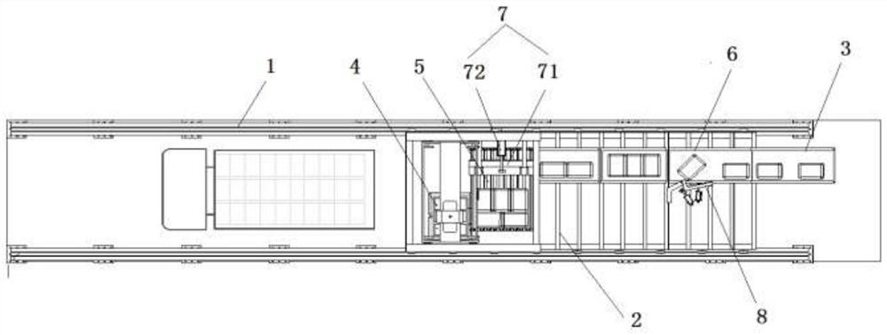
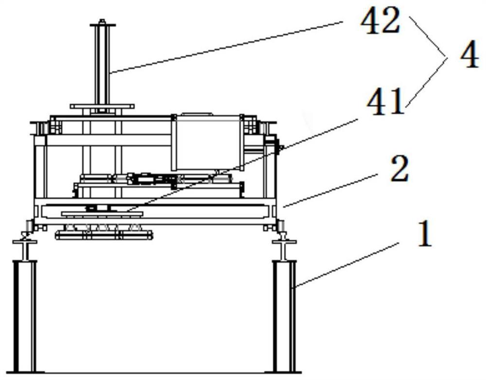
[0024] Such as Figure 1-5 as shown, figure 1 It is a front view of a truss loading system proposed by the present invention; figure 2 It is a top view of a truss loading system proposed by the present invention; image 3 A side view of a truss loading system proposed by the present invention; Figure 4 It is a three-dimensional schematic diagram of the truss trolley in a truss loading system proposed by the present invention; Figure 5 It is a structural schematic diagram of the regularizing mechanism in a truss loading system proposed by the present invention.

[0025] refer to Figure 1-4 , a truss loading system proposed by an embodiment of the present invention, comprising: a truss 1, a truss trolley 2 and a conveying line 3, wherein: the truss 1 includes a first side frame and a second side frame, and the first side frame, the second side frame Th...


PUM


Abstract

The invention discloses a truss loading system, comprising: a truss, a truss trolley, and a conveying line, wherein: the truss includes a first side frame and a second side frame, and the first side frame and the second side frame are arranged oppositely and positioned between the two Spaces are reserved between them to form the aisle for supply trucks to pass through; the truss trolley is located above the first side frame and the second side frame and connected with the first side frame and the second side frame respectively, and the truss trolley is preset with discharge Area, the discharge area is equipped with a discharge device for sequentially arranging the incoming bagged materials; the bagged material transfer device for transferring the bagged materials in the discharge area to the truck is installed on the truss trolley; The conveying line is located above the first side frame and the second side frame for conveying the bagged materials to be loaded to the direction of the discharge area, and the output end of the conveying line is lower than its input end. The invention can effectively increase the loading speed and improve the neatness of bagged material loading.

Description

technical field [0001] The invention relates to the technical field of automatic transportation, in particular to a truss loading system. Background technique [0002] With the development of the economy, the production level continues to increase. After the production of finished materials in bags such as cement and flour, the materials need to be placed on the transport vehicle. At present, most of them are handled manually. This method of handling not only consumes human resources, but also And loading speed is slow, and efficiency is low. Contents of the invention [0003] Based on the technical problems in the above background technology, the present invention proposes a truss loading system. [0004] The present invention proposes a truss loading system, including: a truss, a truss trolley and a conveying line, wherein: [0005] The truss includes a first side frame and a second side frame, the first side frame and the second side frame are arranged oppositely and ...

Claims


Application Information

Patent Timeline
Patent Type & Authority Patents(China)
IPC IPC(8): B65G67/04B65G47/26B65G57/24B65G61/00
CPCB65G47/26B65G57/24B65G61/00B65G67/04
Inventor 符荣华张聪陈龙王雪松
Owner 芜湖固高自动化技术有限公司
Learn More