High-precision adjustable bottle mould

A high-precision, pedestal technology, applied in bottle filling, liquid bottling, packaging, etc., can solve problems such as damage to special-shaped bottles, failure to maintain vertical state of special-shaped bottles, and shaking, etc., to achieve the effect of improving speed and quality

Active Publication Date: 2018-12-25
常州市泰瑞包装科技有限公司
View PDF2 Cites 2 Cited by
  • Summary
  • Abstract
  • Description
  • Claims
  • Application Information

AI Technical Summary

Problems solved by technology

[0004] Although the above-mentioned patent can solve the problem that the special-shaped bottle cannot maintain a consistent vertical state during the conveying and filling process, in order to reduce the quality of the conveying device during the conveying process of the special-shaped bottle, the device must It needs to be separated from the adjusting motor in the process of transportation, and shaking will inevitably occur during the transportation process. The positive and negative screw rods are installed on the bearing seats at both ends of the slide rail, and there is no device to fix the positive and negative screw rods. Long-term shaking It will drive the positive and negative screw to rotate, and the rotation of the positive and negative screw will drive the left and right jaws to follow the left-handed nut block and the right-handed nut block to move relatively or in the opposite direction, and the relative movement of the left and right jaws will The special-shaped bottle is damaged; the left jaw and the right jaw move oppositely, and the left and right jaws will separate the special-shaped bottle, and the special-shaped bottle will not be clamped, so that the special-shaped bottle cannot be kept during the conveying and filling process. consistent vertical state

Method used


Image

  • High-precision adjustable bottle mould
  • High-precision adjustable bottle mould
  • High-precision adjustable bottle mould

Examples


Embodiment 1

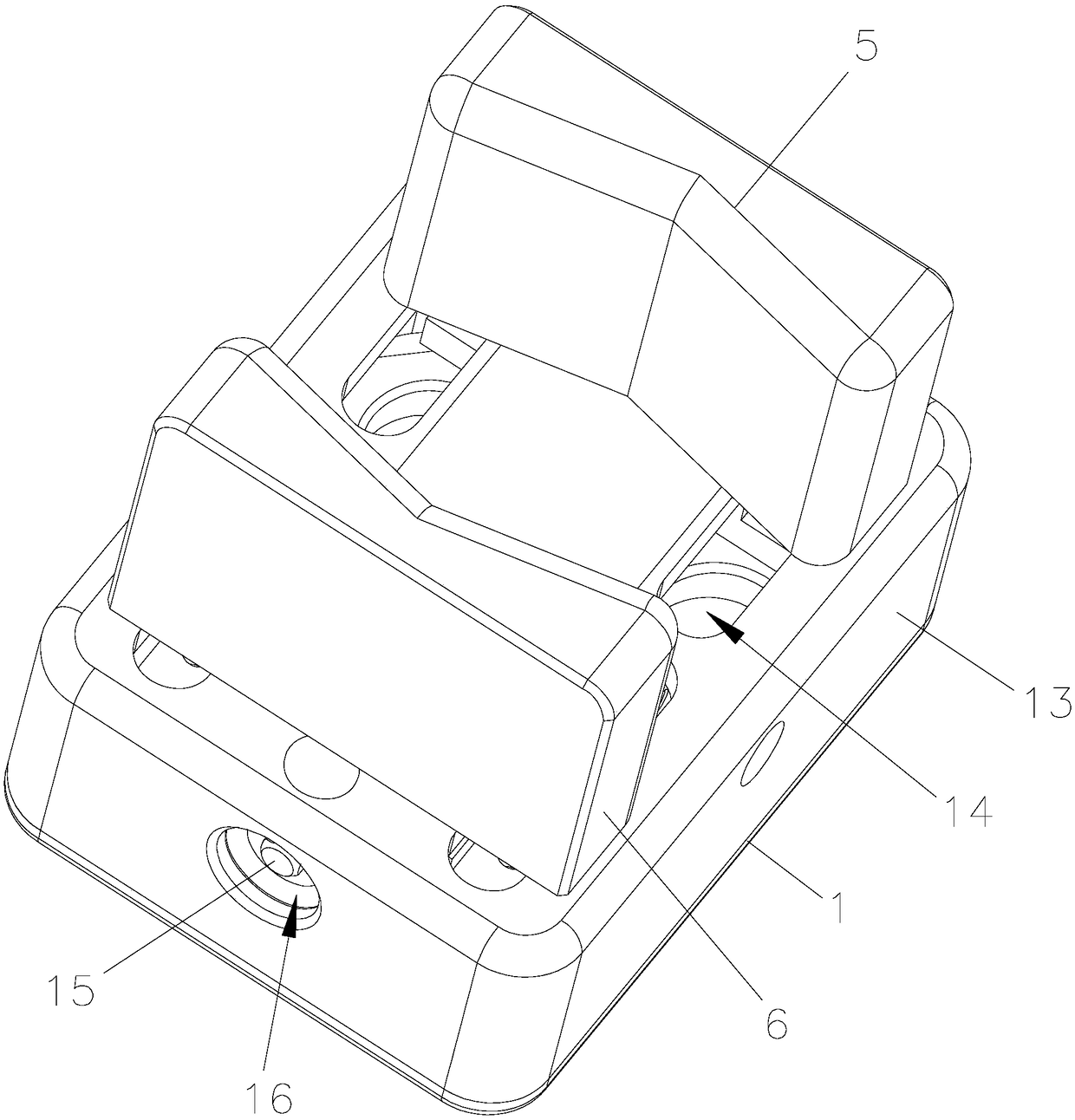
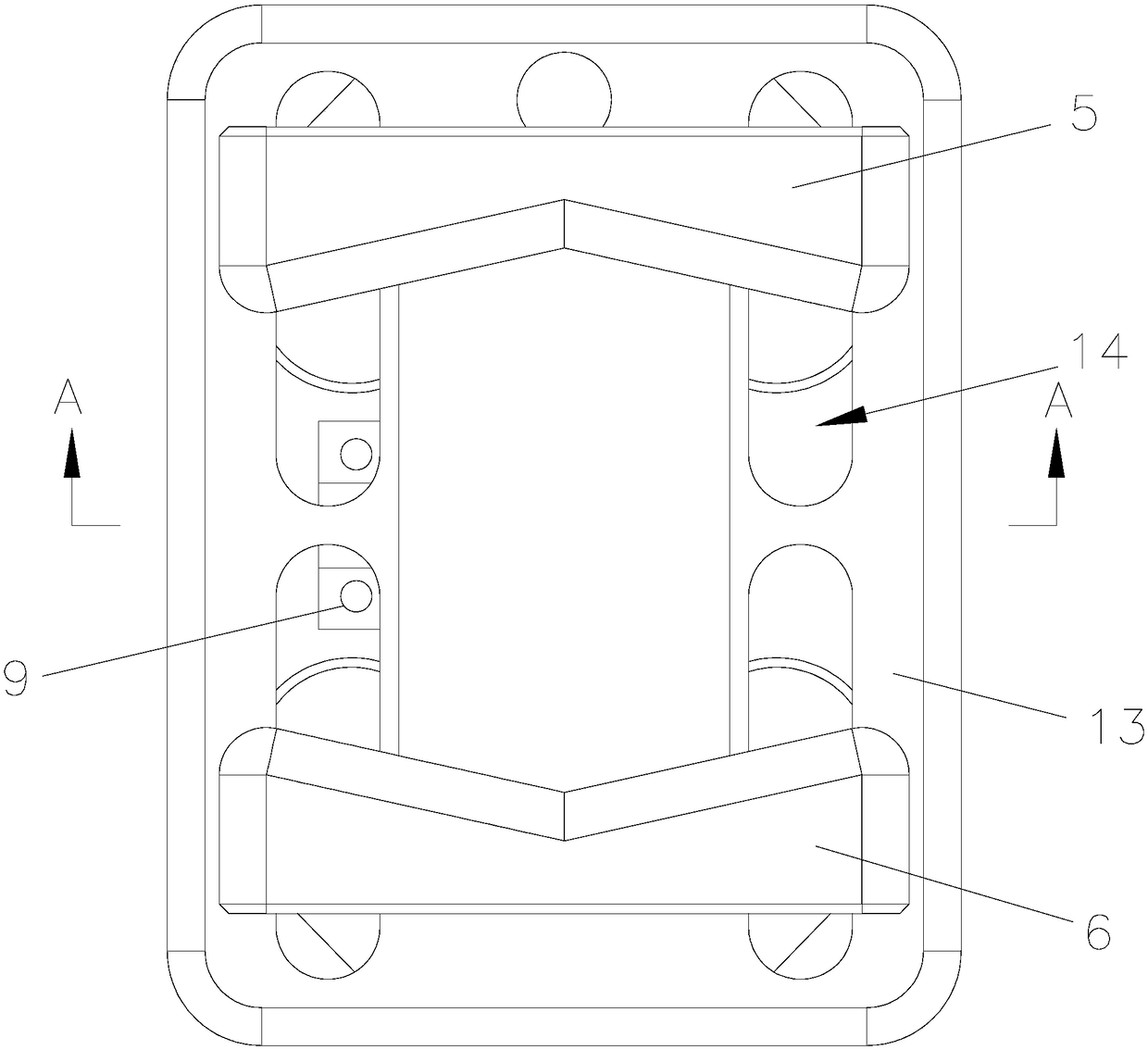
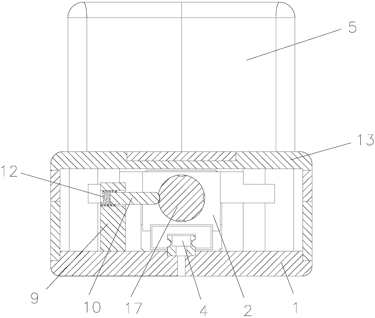
[0028] Such as figure 1 , figure 2 , Figure 4 and Figure 6 A high-precision adjustable bottle mold shown includes a base 1, on which a positive and negative screw rod 17 is rotated through a bearing, and left-handed nuts are respectively driven and mounted on both ends of the positive and negative screw rod 17. Block 2 and right-handed nut block 3, the base 1 is provided with a slide rail 4, the left-handed nut block 2 and the right-handed nut block 33 are all slidably arranged on the slide rail 4 by a slider, the Left-handed nut block 2 is fixedly equipped with left jaw 5, as Figure 5 As shown, the right jaw 6 is fixedly installed on the right-handed nut block 3, and the centerlines of the left jaw 5 and the right jaw 6 coincide with the positive and negative screw rods 17, and the middle of the positive and negative screw rods 17 Coaxially fixedly install the limit ring 7 at the position, such as image 3 As shown, four limit holes 8 are evenly opened on the outer c...

Embodiment 2

[0033] Such as Figure 8 The difference between the illustrated embodiment 2 and the embodiment 1 is that the elastic element is a rubber column 11, one end of the rubber column 11 is fixedly connected with the inner wall of the installation hole, and the other end is connected with one end of the limit rod 10 End face fixed connection.


PUM


Abstract

The invention relates to a high-precision adjustable bottle mould. A limit ring is coaxially and fixedly mounted on a front screw rod and a back screw rod, a plurality of limit holes are uniformly formed on the outer circumferential surface of the limit ring, and a limit seat is fixedly mounted on a base. The limit seat is retractably provided with a limit rod. After the positional relationship between a left jaw and a right jaw is adjusted by the front screw rod and the back screw rod, the limit rod is inserted into the limit hole. The limit rod limits the rotation of the front screw rod andthe back screw rod, and fixes the positional relationship between the left jaw and the right jaw. During transportation of shaped bottles, the front screw rod and the back screw rod do not rotate dueto shaking. The left jaw and the right jaw always hold the shaped bottles, and the shaped bottles can always maintain a consistent vertical state during the filling process, speed and quality of cansare improved.

Description

technical field [0001] The invention relates to the technical field of packaging machinery, in particular to a high-precision adjustable bottle mold. Background technique [0002] With the improvement of people's material living standards, people put forward diversified artistic requirements for the packaging of commodities, and people prefer to buy all kinds of commodities with artistic and aesthetic packaging. In recent years, more and more high-end daily chemical products are packaged in colorful The special-shaped bottle packaging greatly improves the packaging grade of the product, and is more popular with people. Due to the particularity of the special-shaped bottle, the bottom of the bottle is non-flat and cannot be placed directly on the conveyor belt for filling. With the side rib limit on both sides, it cannot ensure that the special-shaped bottle maintains a consistent vertical state during the conveying and filling process. [0003] The Chinese patent with the p...

Claims


Application Information

Patent Timeline
Patent Type & Authority Applications(China)
IPC IPC(8): B67C3/24
CPCB67C3/24
Inventor 毛志军徐方亭杨波吴洪明
Owner 常州市泰瑞包装科技有限公司
Why Eureka
Try Eureka