Composite mechanism for inspection well safety and anti-falling

A safe and anti-drop technology, which is applied to underwater structures, infrastructure engineering, construction, etc., can solve the problems of not alleviating the loss of manhole covers, achieve good fixation, increase drainage, and strengthen structural stability

Active Publication Date: 2019-07-30
CHENGDU ZHIRONG ZHICHUANG INTPROP MANAGEMENT CO LTD
View PDF4 Cites 0 Cited by
  • Summary
  • Abstract
  • Description
  • Claims
  • Application Information

AI Technical Summary

Problems solved by technology

[0005] The technical problem to be solved by the present invention is: most of the prior art uses anti-falling nets to prevent people or foreign objects from falling into the well, and it does not alleviate the problem that the well cover will be lost due to backflow of the pipe network. The present invention provides A composite mechanism for inspection shaft safety and anti-falling that solves the above problems

Method used


Image

  • Composite mechanism for inspection well safety and anti-falling
  • Composite mechanism for inspection well safety and anti-falling
  • Composite mechanism for inspection well safety and anti-falling

Examples


Embodiment 1

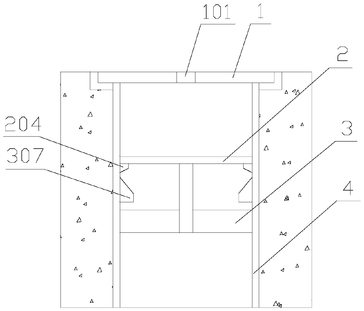
[0043] This embodiment provides a safety and anti-drop composite mechanism for inspection wells, including a well cover 1 and an anti-fall screen 2, the well cover 1 is arranged at the port of the shaft, and the anti-fall screen 2 is arranged in the shaft near the port. That is, the anti-fall net plate 2 includes a positioning cylinder 201, a plurality of radiating ribs 202 and a plurality of reinforcing ribs 203, and a plurality of radiating ribs 202 are evenly distributed and fixed radially along the outer wall of the positioning cylinder 201, and a plurality of reinforcing ribs 203 are all in the form of Circular structure, and the distribution of the coaxial center line with the positioning cylinder 201 strengthens and fixes the radial ribs 202, and multiple reinforcing ribs 203 are distributed at equal intervals along the radial direction of the positioning cylinder 201; the well cover 1 is provided with through holes 101 for water circulation ;

[0044] It also includes ...

Embodiment 2

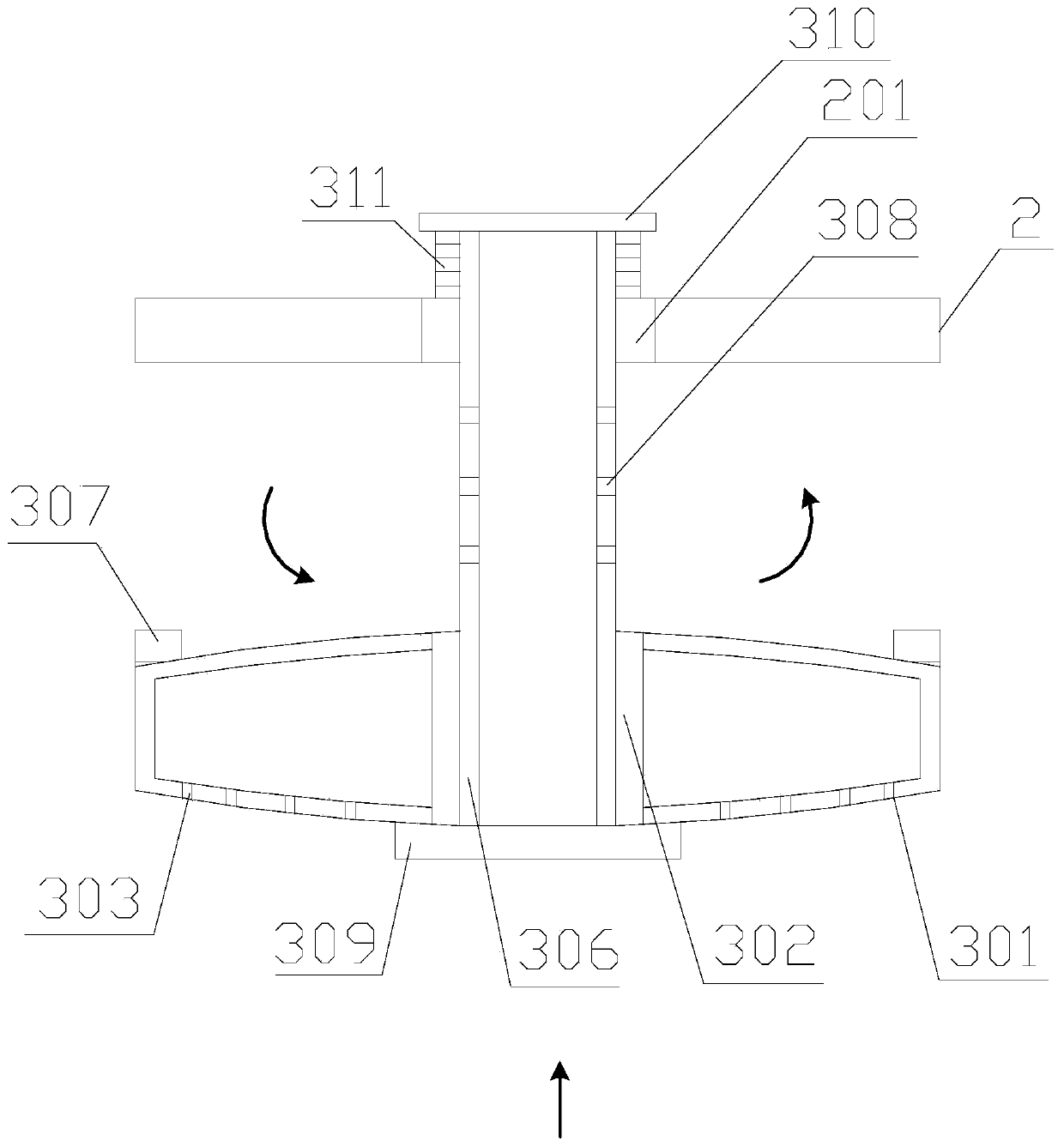
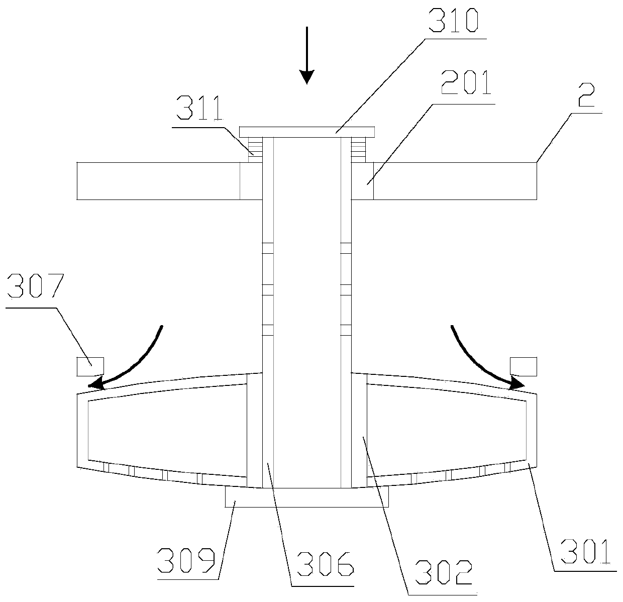
[0047] Further improvement on the basis of Embodiment 1, the positioning cylinder 201 includes a bottom ring plate 2011 and a top ring plate 2012 arranged in parallel, and a sleeve for the center pipe 306 to pass through is provided between the bottom ring plate 2011 and the top ring plate 2012 The tube 2013; the positioning cylinder 201 also includes a plurality of positioning columns 2014, and the plurality of positioning columns 2014 are distributed at equal intervals around the sleeve 2013 in a ring shape, and one axial end of each positioning column 2014 is fixed on the bottom ring plate 2011, The other end in the axial direction is fixed on the top ring plate 2012; the radial rib 202 is provided with a fixed ring 206 at the axial end, and the fixed ring 206 is sleeved on the positioning column 2014 with clearance fit, and the other axial end of the radial rib 202 is fixed by the reinforcing rib 203. The axial bottom ends of the sleeve 2013 and the positioning column 2014 ...

Embodiment 3

[0049] Further improvement on the basis of Embodiment 2, the sealing plates at both axial ends of the outer sleeve 301 are curved plates protruding outward, and the axial section of the outer sleeve 301 has a spindle structure. The first limiting ring 307 is provided with a rubber strip on the surface facing the outer sleeve 301 , and the first limiting ring 307 is in contact with the upper surface of the outer sleeve 301 through the rubber strip. The axial end of the central tube 306 provided with bearings runs through the inner sleeve 302, and the end of the central tube 306 passing through the inner sleeve 302 is provided with a first baffle 309, and the first baffle 309 faces the surface of the outer sleeve 301 The ring is provided with a rubber strip, and the contact between the first baffle plate 309 and the outer sleeve 301 is through the rubber strip.


PUM


Abstract

The invention discloses a safety fall-preventing composite mechanism used for an inspection well. A through hole used for water circulating is formed in a well lid; a fall-preventing screen board comprises a positioning barrel, a plurality of radiant ribs and a plurality of reinforcing ribs, which are distributed in the shape of a spider web by taking the positioning barrel as a center, wherein the axial two end openings of an outer sleeve of a buffer mechanism are sealed by sealing plates; an inner sleeve penetrates through the sealing plates at the axial two end openings of the outer sleeveto be sleeved in the outer sleeve; a plurality of first through holes are formed in the sealing plate at the axial bottom end of the outer sleeve; a plurality of curved blade type strip-shaped shellswhich are distributed in the form of a turbine are arranged on the surface of the sealing plate at the axial top end of the outer sleeve in a convex mode; a plurality of liquid distributing holes areuniformly formed in the same side wall of a housing; the outer wall of one axial end of a central tube is rotatably connected with the inner wall of the inner sleeve through a bearing, and the other axial end of the central tube is movably connected with the positioning barrel; and a plurality of second through holes are formed in the side wall of the central tube. The safety fall-preventing composite mechanism is beneficial for effectively dispersing and weakening strong water flow impact force generated by return overflow, and is beneficial for preventing the well lid from being jacked to lose to cause casualties; and the fall-preventing screen board is stable and safe in structure.

Description

technical field [0001] The invention relates to the technical field of urban road infrastructure, in particular to a safety and anti-drop composite mechanism for inspection wells. Background technique [0002] Manhole cover, the covering on the road, can be seen everywhere in the streets and alleys of cities and towns. It is used to cover roads or deep wells in homes to prevent people or objects from falling. According to the material, it can be divided into metal manhole covers, high-strength fiber cement concrete manhole covers, resin manhole covers, etc. Usually round. It can be used in green belts, sidewalks, motorways, docks, alleys, etc. [0003] Due to the short-term heavy rainfall and insufficient capacity of drainage pipes, once the pipe network leaks water, the impact force will be greater, and the manhole cover will be lifted up or even fly. Passers-by cannot see the situation under their feet. Accidents of washing away occurred, and vehicle damage and personal...

Claims


Application Information

Patent Timeline
Patent Type & Authority Patents(China)
IPC IPC(8): E02D29/12E02D29/14
CPCE02D29/127E02D29/14
Inventor 黄欢
Owner CHENGDU ZHIRONG ZHICHUANG INTPROP MANAGEMENT CO LTD
Why Eureka
Try Eureka