
A Tension Meter Used in Physics Experiments of High School Students

A tension meter and biophysical technology, applied in the field of teaching equipment, can solve problems such as easy damage to force measuring components, changes in the direction of force, and easy shaking in the direction of pulling, so as to avoid leakage and facilitate replacement and maintenance.

Active Publication Date: 2020-12-22
程尚方
View PDF3 Cites 1 Cited by
  • Summary
  • Abstract
  • Description
  • Claims
  • Application Information

AI Technical Summary

Problems solved by technology

[0003] The present invention provides a technical solution, which can effectively solve the above-mentioned background technology. The tensile gauges currently on the market for high school students’ physical experiments have a simple structure. Because the school students’ experiments need to be used more times, the internal force-measuring components are prone to damage. Existing tension gauges need to be disassembled with a screwdriver, which is not conducive to quick repair and replacement of damaged components inside the tension gauge in the classroom, and it is easy to cause the situation that the number of tension gauges damaged is not enough for students to use. At the same time, the hook of the tension gauge is stretched during the pulling process. The rope that comes out and the direction that the user pulls tend to shake, which causes the direction of the force to change all the time, which is not conducive to the problem that high school students can accurately understand the movement of the object after the force is applied during the experiment.

Method used


Image

  • A Tension Meter Used in Physics Experiments of High School Students
  • A Tension Meter Used in Physics Experiments of High School Students
  • A Tension Meter Used in Physics Experiments of High School Students

Examples


Embodiment Construction

[0020] The preferred embodiments of the present invention will be described below in conjunction with the accompanying drawings. It should be understood that the preferred embodiments described here are only used to illustrate and explain the present invention, and are not intended to limit the present invention.

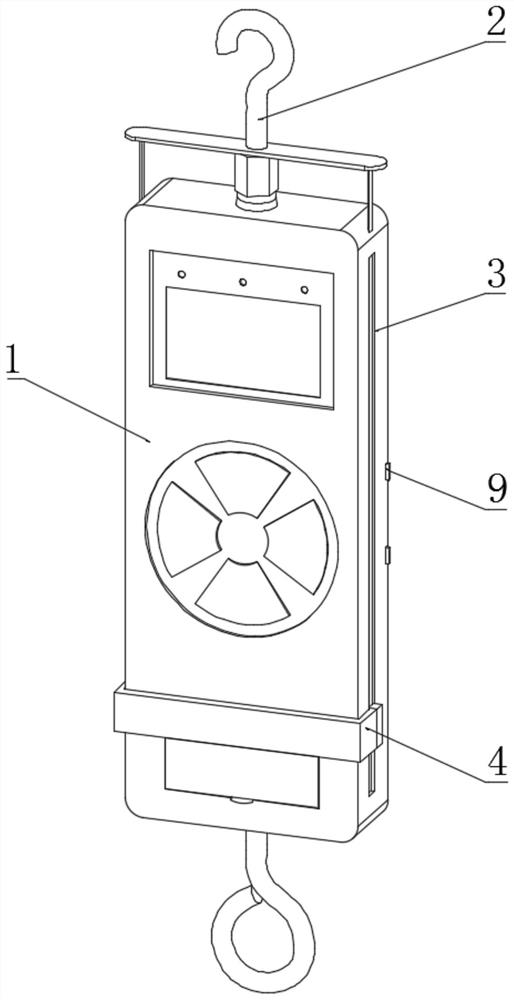
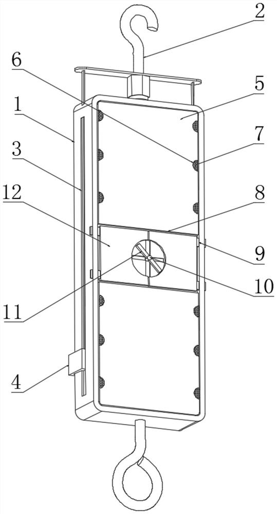
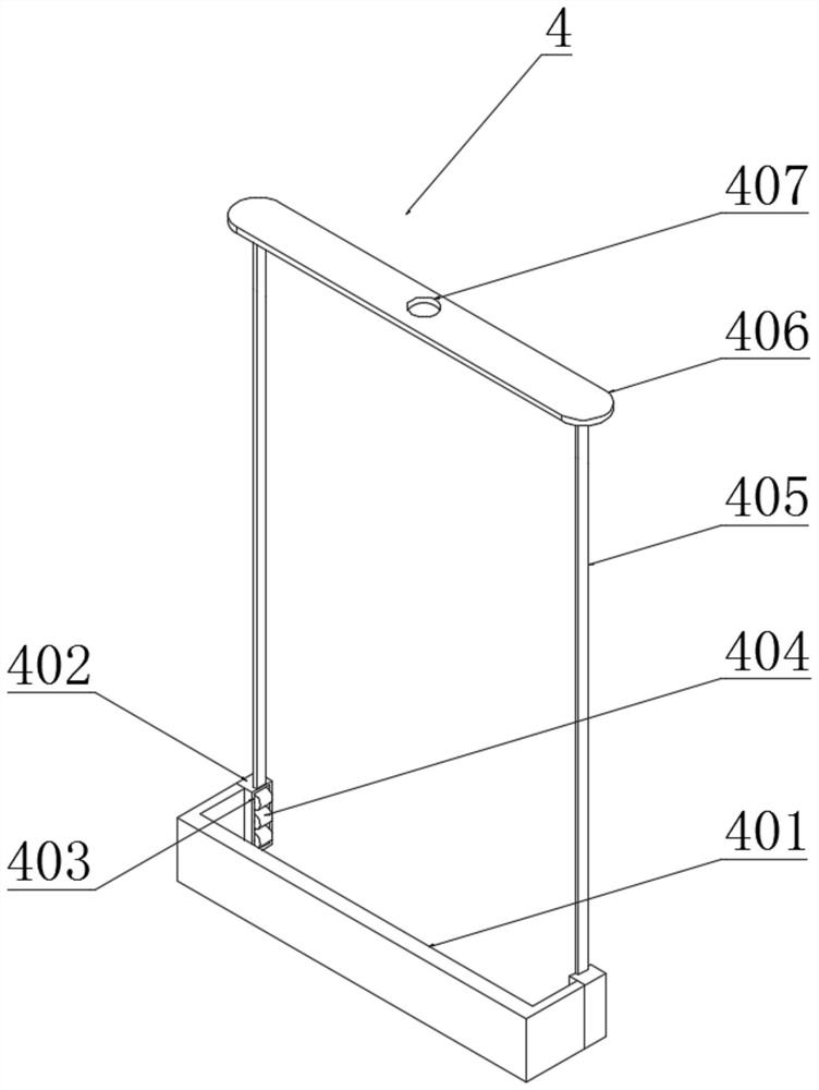
[0021] Example: such as Figure 1-4 As shown, the present invention provides a technical solution, a tension meter used for high school students' physics experiments, comprising a tension gauge housing 1, a hook 2 is installed on the top of the tension gauge housing 1, and the side surface of the tension gauge housing 1 has limited openings. Position chute 3, anti-sway mechanism 4 is installed inside the limit chute 3, anti-sway mechanism 4 comprises slide plate 401, slide block 402, mounting groove 403, roller 404, connecting rod 405, support plate 406 and through hole 407, A slide plate 401 is installed on one side of the tension gauge housing 1, a slide block 402...


PUM


Abstract

The invention discloses a tension gauge for physical experiments of senior high school students. The tension gauge comprises a tension gauge shell, a limiting sliding groove is formed in the side surface of the tension gauge, and an anti-shaking mechanism is mounted in the limiting sliding groove. The tension gauge is scientific and reasonable in structure and safe and convenient to use, under thelimiting action of the limiting sliding groove and a sliding block, a supporting plate is attached to a hook through a through hole, so that it is guaranteed that a rope and a connecting rod are keptin parallel after the hook extends out, it is guaranteed that the pulling direction and the initial direction of the tension gauge are the same, when the senior high school students make experiments,it can be always guaranteed that the pulling direction of the tension gauge is kept unchanged, it is guaranteed that the stress state and the initial state of an object are consistent, and the seniorhigh school students can learn the state after physical stress better. After a clamping rod is rotated, a clamping plate can be taken out, a rear cover can be dismounted conveniently, internal components of the tension gauge can be replaced and maintained conveniently, and the condition that part of senior high school students can not make experiments due to damage of the tension gauge is avoided.

Description

technical field [0001] The invention relates to the technical field of teaching appliances, in particular to a tension meter used for physics experiments of high school students. Background technique [0002] The tension meter is a small and simple thrust and tension testing instrument, which has the advantages of high precision, easy operation and portability, and has a peak value switching operation knob, which can be used for peak load indication and continuous load value indication. In the physics experiment of high school students, Often choose to use the tension meter as a tool to measure gravity. At the same time, in the physics laboratory of high school students, according to the knowledge in books, there will often be a physics that is affected by ri of different sizes in multiple directions. At this time, the tension meter can act as a non-gravity instrument Stress in other directions, because the value generated during the pulling process of the tension gauge is a...

Claims


Application Information

Patent Timeline
Patent Type & Authority Patents(China)
IPC IPC(8): G01N3/08G01L1/26
CPCG01L1/26
Inventor 程尚方
Owner 程尚方
Learn More