Enable-control circuit

A technology for controlling circuits and circuits, which is applied in electrical components, electronic switches, pulse technology, etc., and can solve problems such as long operation time and board damage.

Active Publication Date: 2018-12-25
ZHENGZHOU YUNHAI INFORMATION TECH CO LTD
View PDF4 Cites 0 Cited by
  • Summary
  • Abstract
  • Description
  • Claims
  • Application Information

AI Technical Summary

Problems solved by technology

[0005] The purpose of the present invention is to provide an enabling control circuit, which can solve the problem that the operation takes a long time and is easy to cause damage to the board existing in the way of controlling the enabling input end of the VR circuit in the prior art

Method used


Image

  • Enable-control circuit
  • Enable-control circuit
  • Enable-control circuit

Examples


Embodiment Construction

[0022] The technical solutions in the embodiments of the present invention will be clearly and completely described below in conjunction with the accompanying drawings in the embodiments of the present invention. Obviously, the described embodiments are only a part of the embodiments of the present invention, rather than all the embodiments. Based on the embodiments of the present invention, all other embodiments obtained by those of ordinary skill in the art without creative work shall fall within the protection scope of the present invention.

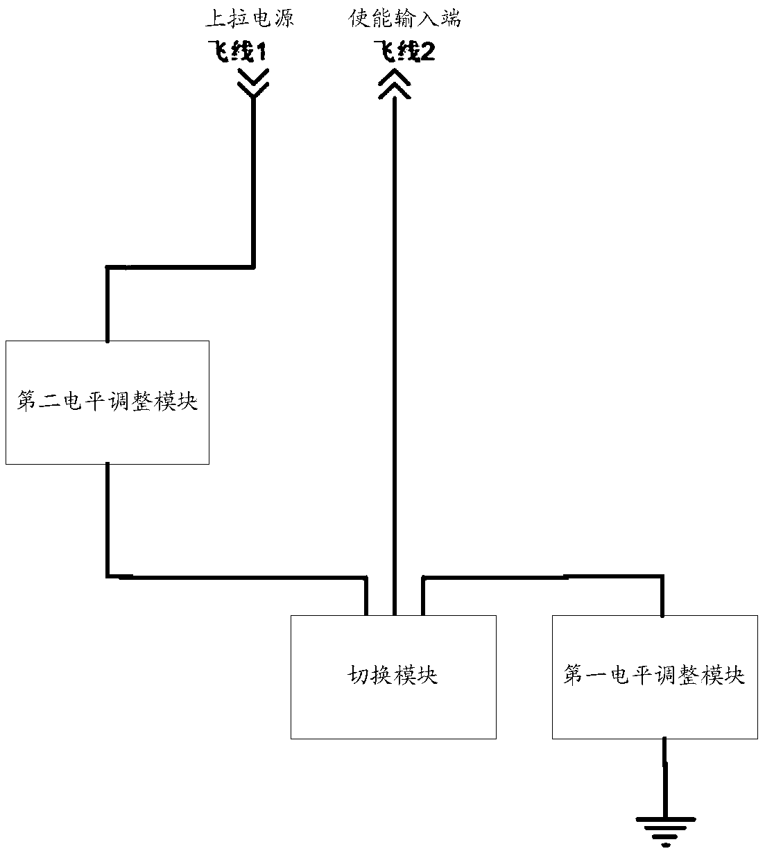
[0023] See figure 2 , Which shows a schematic diagram of an enable control circuit provided by an embodiment of the present invention, which may include a first level adjustment module, a second level adjustment module, and a switching module; the switching module and the enabling of the VR circuit of the board The input terminal is connected through a flying lead; one end of the first level adjustment module is connected to the switchin...


PUM


Abstract

The invention discloses an enable-control circuit, which comprises a first level adjusting module, a second level adjusting module and a switching module. The switch module is connected with the enable input terminal of the VR circuit of the board through a flying wire. The switch module is connected with the enable input terminal of the VR circuit of the board through a flying wire. One end of the first level adjusting module is connected with the switching module, and the other end is grounded for controlling the input level of the enabling input terminal to be changed from a high level to alow level when the switching module controls the enabling input terminal to be connected with the first level adjusting module; one end of the second level adjusting module is connected with the switching module, and the other end is connected with the pull-up power supply of the board, which is used for controlling the input level of the enable input terminal to be changed from the low level tothe high level when the switching module controls the enable input terminal to be connected with the second level adjusting module. Thus, in the technical proposal disclosed in the present application, the operation of removing the resistor R13 is canceled, and only the flying wire used for welding is required, the operation time is short, and the damage to the board is largely avoided.

Description

Technical field [0001] The invention relates to the technical field of board card VR timing testing, and more specifically, to an enabling control circuit. Background technique [0002] During the board VR (voltage conversion circuit / voltage converter) timing test, due to the circuit delay of the multi-level VR and the firmware difference of the control signal, the AC terminal of the power module that normally plugs and unplugs the power supply for the board cannot be collected accurately Reflect the waveform of the VR timing. At this time, it is necessary to directly control the VR's EN enable pin (enable input) to measure the VR power-on timing. [0003] figure 1 It is the EN pin enable circuit commonly used in VR. Among them, U1 and the right circuit are VR circuits. The existing measurement method is to remove the R13 resistor and replace it with a single switch. By adjusting the on and off of the switch, the VR can be achieved. Power on and off control. However, this method ...

Claims


Application Information

Patent Timeline
IPC IPC(8): H03K17/687
CPCH03K17/687
Inventor 齐雪宝
Owner ZHENGZHOU YUNHAI INFORMATION TECH CO LTD
Why Eureka
Try Eureka