Eye drops container

A technology for eye drops and containers, which is applied in medical containers, drug packaging, ophthalmic treatment, etc. It can solve the problems of short compression distance of bellows-shaped grooves and discharge of eye drops, and achieve the effect of reducing volume and preventing overdose

Inactive Publication Date: 2018-12-28
HUONS
View PDF12 Cites 0 Cited by
  • Summary
  • Abstract
  • Description
  • Claims
  • Application Information

AI Technical Summary

Problems solved by technology

However, in this structure, the bellows type slot has a short compression distance
Therefore, when the user

Method used


Image

  • Eye drops container
  • Eye drops container
  • Eye drops container

Examples


Example Embodiment

[0046] The present invention will now be described in more detail with reference to the accompanying drawings.
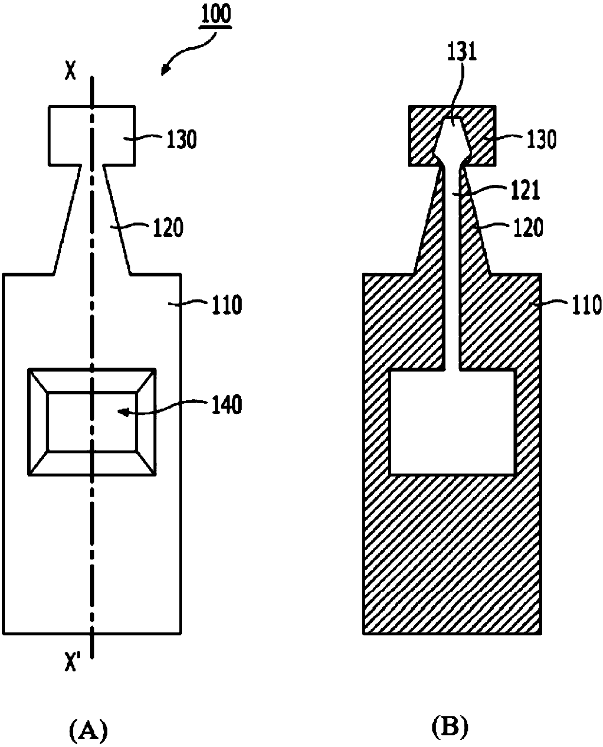
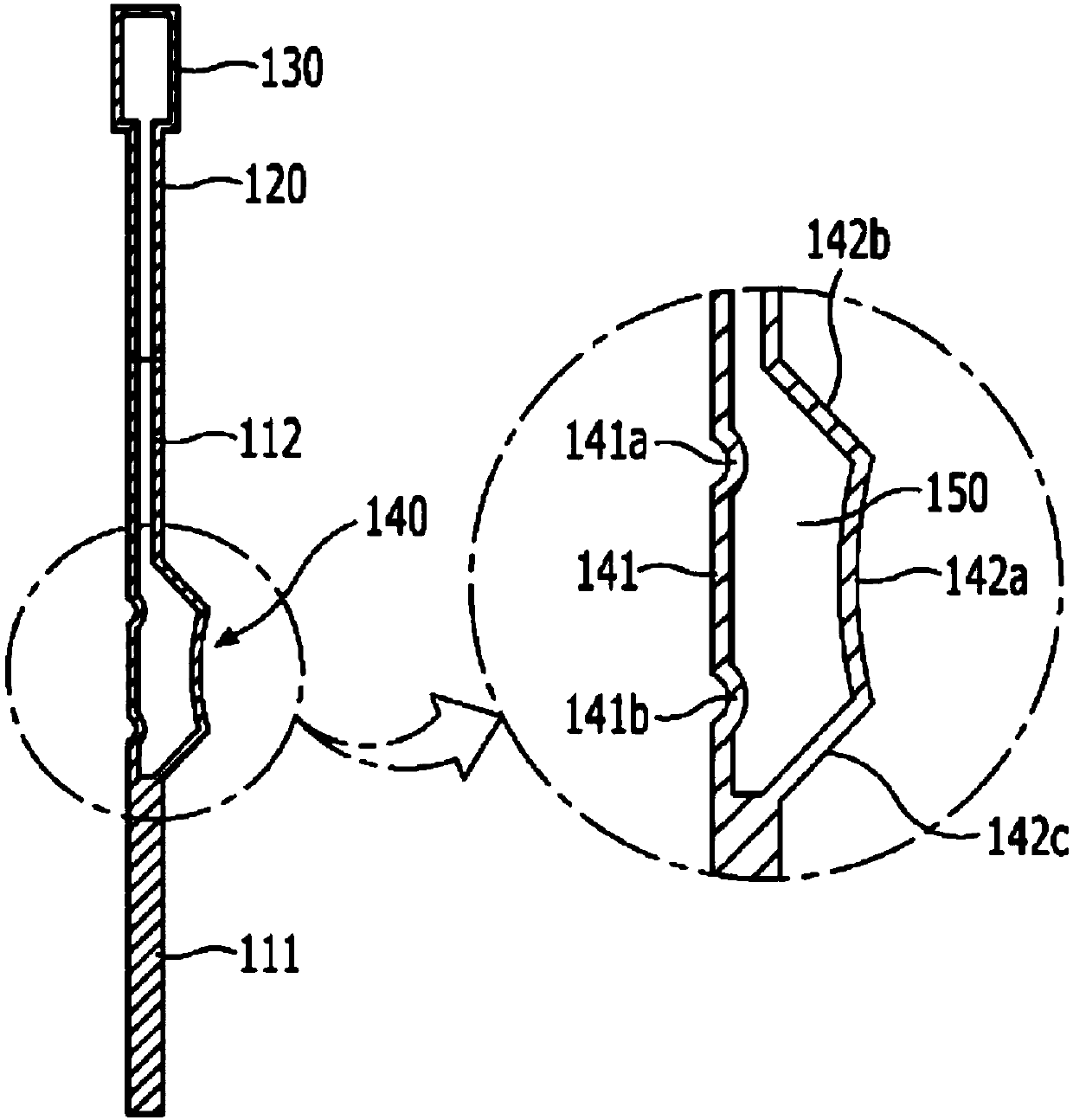
[0047] The eye drop container of the present invention includes: a container body in which an eye drop groove is formed; an eye drop discharge portion extending from the container body and an eye drop flow path connected to the eye drop outlet formed therein; and a sealing portion connected to The eye drops discharge part, wherein the container body is bent so that the eye drops are discharged from the eye drops tank.
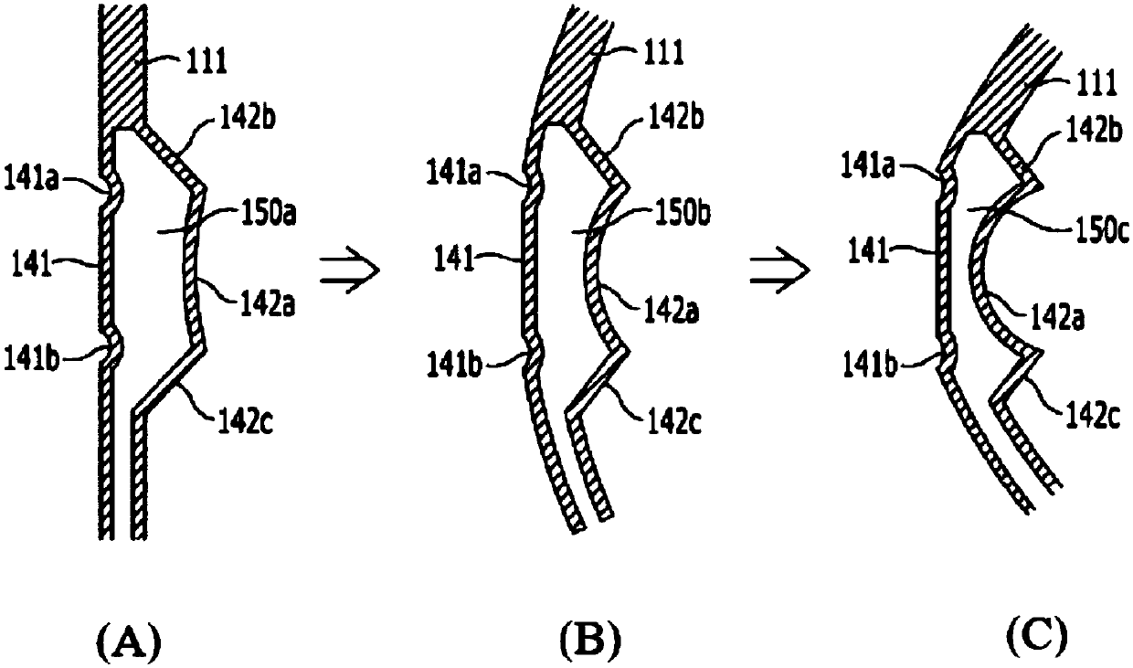
[0048] In a general eye drop container, the eye drop is discharged from the eye drop reservoir by pressing both sides of the eye drop reservoir with fingertips. On the contrary, the discharge of the eye drops from the eye drops container of the present invention is by bending a part of the container body. The eye drop container of the present invention is constructed such that when the container body is bent, a part of the container body is easily bent a...


PUM


Abstract

The invention provides an eye drops container, which includes a container body formed with an eye drops tank, an eye drops discharging part extending from the container body and having an eye drops flow path connected to the eye drops outlet, and a sealing part connected to the eye drops discharging part. The container body is bent so as to discharge the eye drops from the eye drops tank.

Description

technical field [0001] The present invention relates to an eye drop container, and more particularly, to an eye drop container that is easily deformable so that the amount of eye drop discharged to the outside can be easily controlled. Background technique [0002] Eye drops refer to ophthalmic solutions containing physiological saline, which are widely used to treat and improve eye diseases such as eye congestion and dry eye. Eye drops are usually stored in airtight containers for sale and distribution. The eye drops container is individually wrapped and is torn open to drop the eye drops into the eye. [0003] An eye drop container is generally manufactured by a method comprising blowing gas into a mold filled with a material for an eye drop container to process the material into a molded article having a predetermined shape, filling the molded article with a liquid The molded article is sealed in the inner space and by heating the inlet of the molded article through whi...

Claims


Application Information

Patent Timeline
IPC IPC(8): A61F9/00
CPCA61F9/0008A61J1/1475B65D1/08B65D47/18
Inventor 赵在珉高大雄金倍永吴畯教
Owner HUONS
Why Eureka
Try Eureka