
A radio frequency remote method, device and system

A technology of remote radio frequency and remote radio unit, which is applied in transmission systems, wireless communications, electrical components, etc., and can solve problems such as service blind spots, call drops, and inability to move

Active Publication Date: 2020-10-23
DATANG MOBILE COMM EQUIP CO LTD
View PDF7 Cites 0 Cited by
  • Summary
  • Abstract
  • Description
  • Claims
  • Application Information

AI Technical Summary

Problems solved by technology

[0004] Base station site selection The site selection of the base station needs to be based on the geographical location and the factors limited by the property, relying on the transmission of wired connections. The newly added site needs to be deployed with wired and optical cables at the same time. After the base station system is opened, the base station system is relatively fixed. Unable to move, if there is a blind spot in the coverage area of ​​the base station, it will lead to a service blind spot, and when the user enters the service blind spot area from the base station coverage area, it will cause problems such as call drop

Method used


Image

  • A radio frequency remote method, device and system
  • A radio frequency remote method, device and system
  • A radio frequency remote method, device and system

Examples


Embodiment Construction

[0026] In order to supplement the blind spot area covered by the activated base station and solve the call drop problem when the UE enters the blind spot area, the embodiments of the present invention provide a radio remote method, device and system.

[0027] The preferred embodiments of the present invention will be described below in conjunction with the accompanying drawings. It should be understood that the preferred embodiments described here are only used to illustrate and explain the present invention, and are not intended to limit the present invention, and in the absence of conflict, the present invention The embodiments and the features in the embodiments can be combined with each other.

[0028] In order to better understand the embodiment of the present invention, the following first introduces the working principle of the RRU, wherein the optical fiber remote technology is used between the BBU and the RRU, that is, the optical fiber is used to remote the digital ba...


PUM


Abstract

Radio frequency remote method, device and systems are disclosed. The RRU is added on the basis of the original coverage area of the base station system, the RRU accesses the original base station system by using the radio bearer between the UE and the base station system. The RRU can be deployed movably or fixedly according to actual needs, and forms complementary coverage area with the original base station system, supplements the coverage blind spot area, and solves the call dropping problem after the UE enters the coverage blind spot area of the original base station system. The radio frequency remote method comprises the following steps: a first radio frequency remote unit RRU receives a communication address sent by a first user equipment UE, wherein, the communication address is obtained after the first UE accesses a base station system; according to the communication address, the first RRU establishes a new cell using a radio bearer between the first UE and the base station system as a transmission link, the base station system comprising a base station, a baseband processing unit BBU and a second RRU.

Description

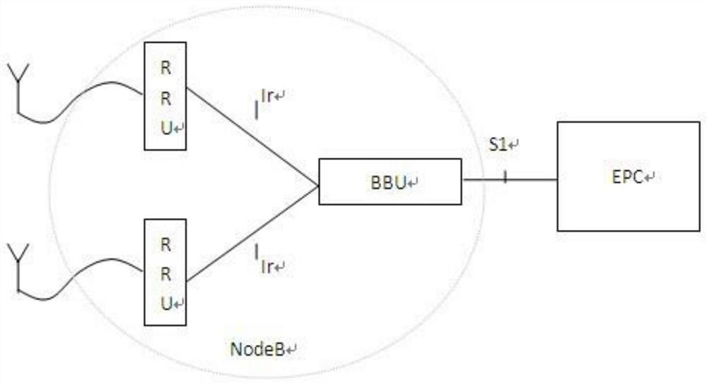
technical field [0001] The present invention relates to the technical field of wireless communication, in particular to a radio remote method, device and system. Background technique [0002] This section is intended to provide a background or context for implementations of the invention that are recited in the claims. The descriptions herein are not admitted to be prior art by inclusion in this section. [0003] The LTE (Long Time Evolution, long-term evolution) base station system is distributed, and it is composed of a baseband processing unit (BBU, Building Base band Unit), a remote radio unit (RRU, Radio Remote Unit) and a base station (eNodeB), such as figure 1 shown. The RRU is connected to the baseband unit device BBU through the Ir interface, and the BBU is connected to the EPC (Evolved Packet Core, evolved packet core network) through the S1 interface. The connection between the BBU and the EPC is through a private PTN (Packet Transport Network, Packet Transport...

Claims


Application Information

Patent Timeline
Patent Type & Authority Patents(China)
IPC IPC(8): H04B1/40H04W88/08
CPCH04B1/40H04W88/085
Inventor 李彪刘春张晓奎
Owner DATANG MOBILE COMM EQUIP CO LTD
Learn More